• DOK-DIAX02-DDS02.1*ANA-ANW1-EN-E1,44 • 12.96
91
When this check has been run the position loop can be closed again.
Procedure:
1. Switch the power off.
2. Disconnect the battery power source.
3. Connect up the command conductor and controller enable from the
NC control to the servo drive module.
4. Set the velocity command evaluation on the DDS 2.1.
(see Section 7.6, Velocity command)
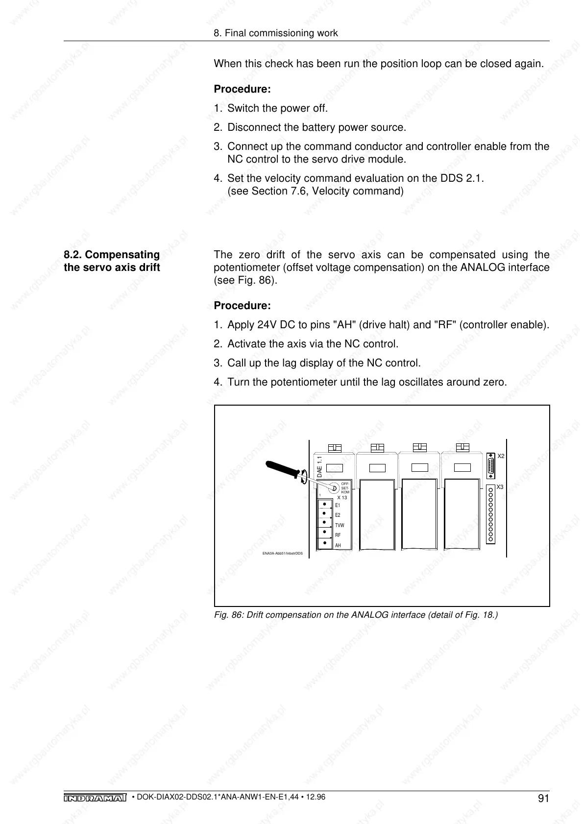
The zero drift of the servo axis can be compensated using the
potentiometer (offset voltage compensation) on the ANALOG interface
(see Fig. 86).
Procedure:
1. Apply 24V DC to pins "AH" (drive halt) and "RF" (controller enable).
2. Activate the axis via the NC control.
3. Call up the lag display of the NC control.
4. Turn the potentiometer until the lag oscillates around zero.
8.2. Compensating
the servo axis drift
8. Final commissioning work
Fig. 86: Drift compensation on the ANALOG interface (detail of Fig. 18.)
ENA3A-Abb51/InbetrDDS
E1
E2
TVW
RF
AH
DAE 1.1
1
OFF-
SET-
KOM
X 13
X3
X2