• DOK-DIAX02-DDS02.1*ANA-ANW1-EN-E1,44 • 12.96
116
11. Appendix
11.6. Pin allocations/
abbreviations
on drive controller
Pin Signal Meaning
X1/1 UD
Error message from supply module
X1/2 BB
Ready message from drive controller
to supply module
X1/3 +15V
15 V supply voltage
X1/4 to X1/7 0VM
0 Volt test voltage
X1/8 to X1/9 -15V
-15V supply voltage
X1/10 0VL
0V load voltage
X1/11 +24V
+24V supply voltage
X1/12
Earth
Pin Signal Meaning
X2/1 0VM
0V test voltage
X2/2 TXD
Transmit data
X2/3 RXD
Receive data
X2/4 RTS
Request to send
X2/5 CTS
Clear to send
X2/10
Earth
Pin Signal Meaning
X3/1 AK1
Analog output channel 1
X3/2 0VM
0V test voltage
X3/3 AK2
Analog output channel 2
X3/4 0VM
0 V test voltage
X3/5
Earth
X3/6, X3/7 Bb
Potential-free signal contact "Ready"
X3/8 AS+
Safety lockout
X3/9 AS-
Safety lockout
X3/10 ASQ Accept safety lockout
X3/11 ASQ Accept safety lockout
Pin Signal Meaning
X4/1
Earth
X4/2 S-
Signal conductor
X4/3 C-
Signal conductor
X4/4 0VM
0V test voltage
X4/7 SCL
Signal conductor
X4/8 SDO
Signal conductor
X4/9 S+
Signal conductor
X4/10 C+
Signal conductor
X4/12 UG
Signal conductor
X4/14 FS
Signal conductor
X4/15 SDI
Signal conductor
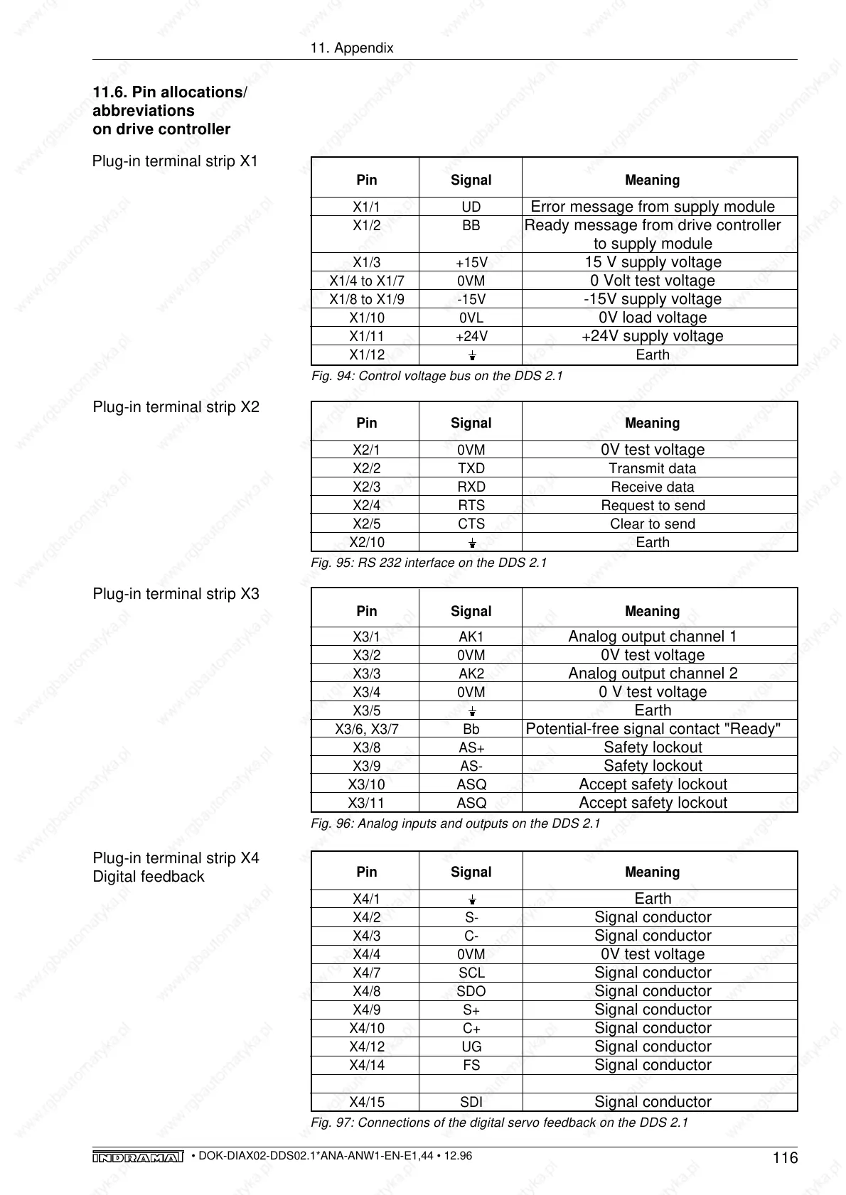
Plug-in terminal strip X1
Plug-in terminal strip X2
Fig. 95: RS 232 interface on the DDS 2.1
Fig. 96: Analog inputs and outputs on the DDS 2.1
Plug-in terminal strip X3
Plug-in terminal strip X4
Digital feedback
Fig. 97: Connections of the digital servo feedback on the DDS 2.1
Fig. 94: Control voltage bus on the DDS 2.1