• DOK-DIAX02-DDS02.1*ANA-ANW1-EN-E1,44 • 12.96
117
11. Appendix
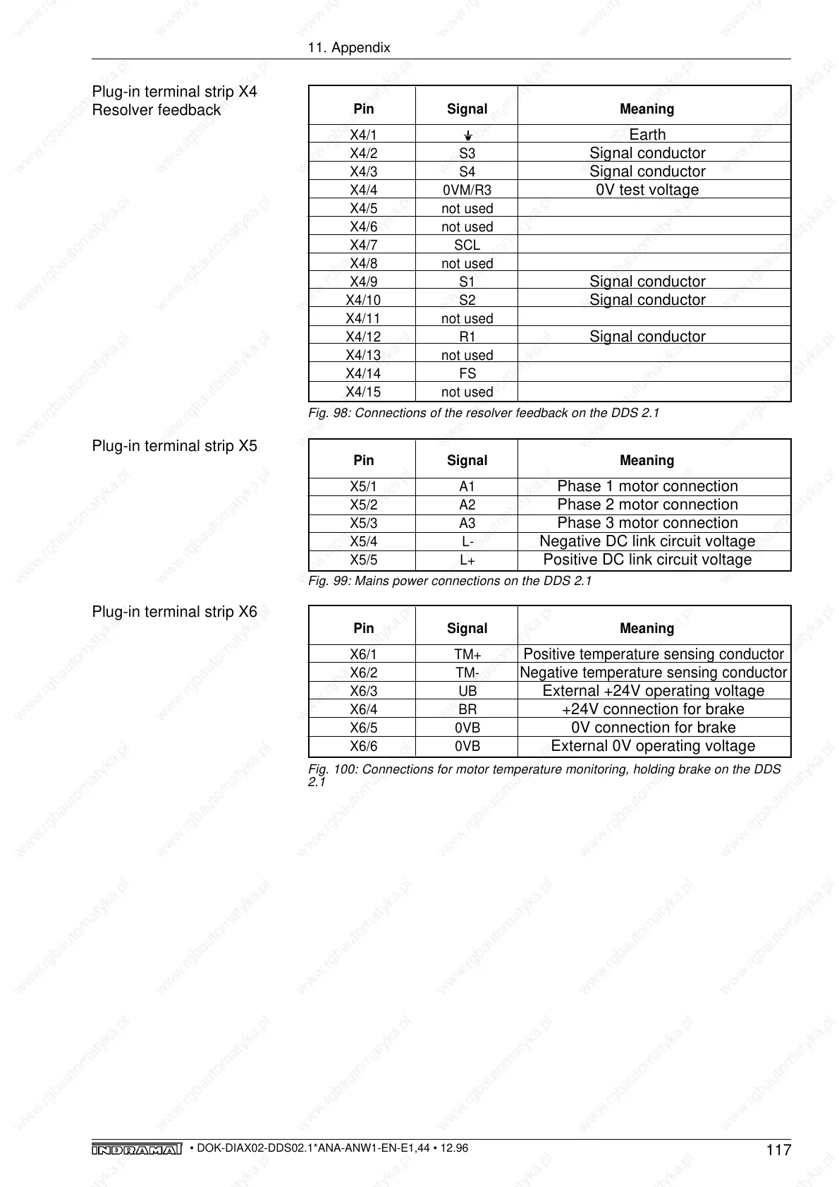
Plug-in terminal strip X4
Resolver feedback
Pin Signal Meaning
X4/1
Earth
X4/2 S3
Signal conductor
X4/3 S4
Signal conductor
X4/4 0VM/R3
0V test voltage
X4/5 not used
X4/6 not used
X4/7 SCL
X4/8 not used
X4/9 S1
Signal conductor
X4/10 S2
Signal conductor
X4/11 not used
X4/12 R1
Signal conductor
X4/13 not used
X4/14 FS
X4/15 not used
Pin Signal Meaning
X5/1 A1
Phase 1 motor connection
X5/2 A2
Phase 2 motor connection
X5/3 A3
Phase 3 motor connection
X5/4 L-
Negative DC link circuit voltage
X5/5 L+
Positive DC link circuit voltage
Pin Signal Meaning
X6/1 TM+ Positive temperature sensing conductor
X6/2 TM- Negative temperature sensing conductor
X6/3 UB
External +24V operating voltage
X6/4 BR
+24V connection for brake
X6/5 0VB
0V connection for brake
X6/6 0VB
External 0V operating voltage
Fig. 98: Connections of the resolver feedback on the DDS 2.1
Fig. 99: Mains power connections on the DDS 2.1
Fig. 100: Connections for motor temperature monitoring, holding brake on the DDS
2.1
Plug-in terminal strip X5
Plug-in terminal strip X6