• DOK-DIAX02-DDS02.1*ANA-ANW1-EN-E1,44 • 12.96
16
2. The digital intelligent AC servo drive with ANALOG interface
2.2. Function schematic of
the digital AC servo drive
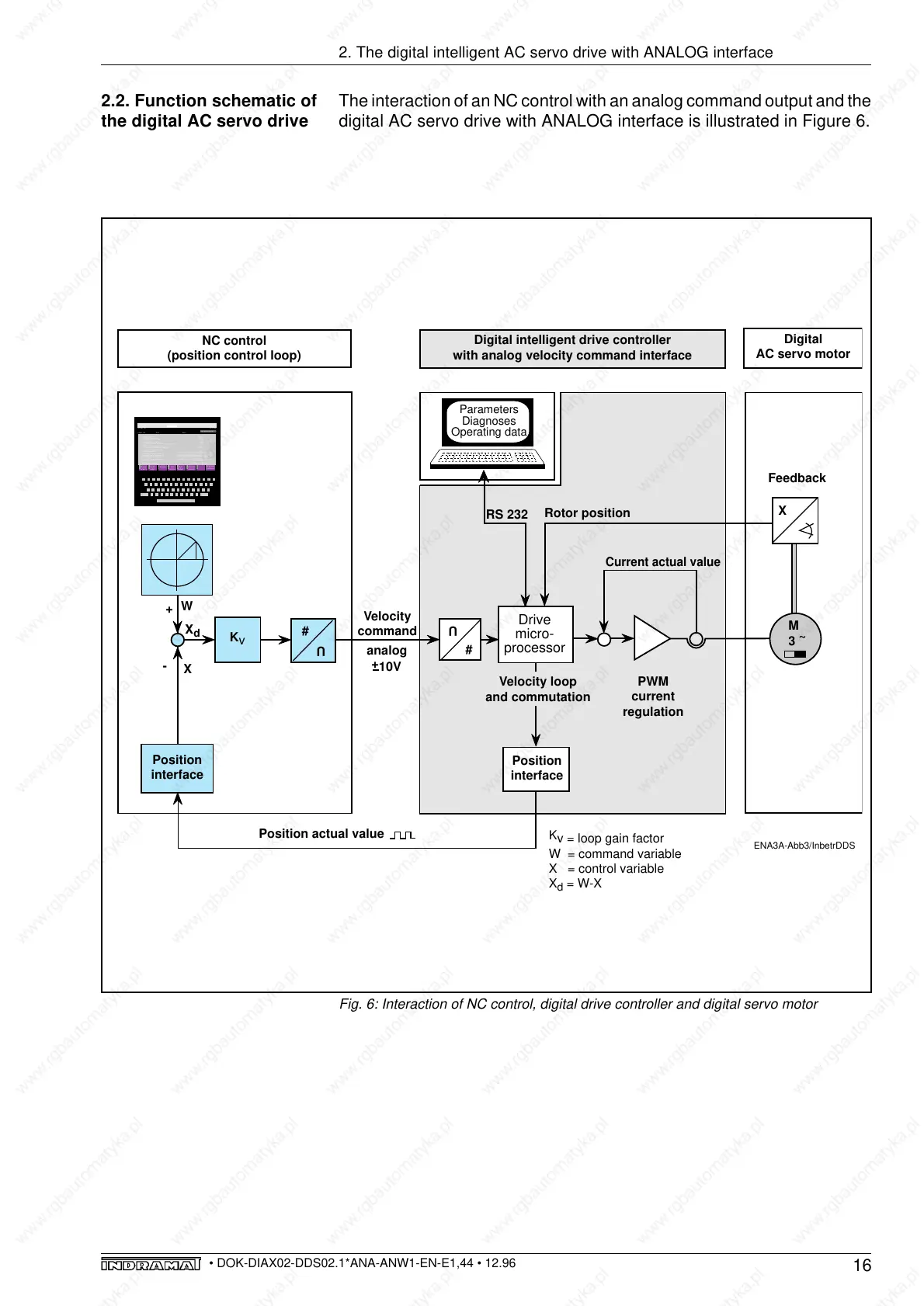
Fig. 6: Interaction of NC control, digital drive controller and digital servo motor
ENA3A-Abb3/InbetrDDS
Velocity loop
and commutation
PWM
current
regulation
Current actual value
Digital intelligent drive controller
with analog velocity command interface
Digital
AC servo motor
Velocity
command
Position actual value
U
#
Rotor position
Feedback
+
10V
M
3
~
analog
NC control
(position control loop)
K
v
+
W
X
-
SERCOS
09-Nov-89
14.13.04
234554
Zum Mech
Überblick
Modus
ändern
1
1 2 3 4 5 6 7 8
Programm
verlassen
File
service
Antriebs
nummer
Dyn.
ändern
Gruppen
Param
ändern
Ident.-Nr. Text
1 NC-Zykluszeit
2 SERCOS Zykluszeit
3 Sende-Reaktionszeit
5 Meßzeit für Istwerte
6 Sendezeitpunkt Antriebs-Telegramm (T1)
7 Meßzeitpunkt der Istwerte
8 Zeitpunkt für Sollwert-Gültig (T3)
9 Anfangsadresse im MDT
10 Länge des MDT
11 STATUS Zustandsklasse-1
12 STATUS Zustandsklasse-2
13 STATUS Zustandsklasse-3
14 STATUS Zustandsklasse-4
15 Telegrammart
32 Hauptbetriebsart
2000 µ
1000 µ
100 µ
80 µ
100 µ
90 µ
1600 µ
R
R
R
R
R
R
00000000000000000000100000000000
00000000000000000000000000000000
00000000000000000000000000000000
00000000000000000000000000000000
0000000000000101
0000000000000010
1
10
Wert
Antriebsnummer 1
Position
interface
X
RS 232
Parameters
Diagnoses
Operating data
U
#
Position
interface
Drive
micro-
processor
X
d
K
v = loop gain factor
W = command variable
X = control variable
X
d
= W-X
The interaction of an NC control with an analog command output and the
digital AC servo drive with ANALOG interface is illustrated in Figure 6.