• DOK-DIAX02-DDS02.1*ANA-ANW1-EN-E1,44 • 12.96
92
8. Final commissioning work
8.3. Checking
the servo drive
Setting the safety limit switch Set the safety limit switch of the axis at an adequate distance from the
fixed stop:
Procedure:
1. Check that the cams are of sufficient length.
2. Traverse the axis at maximum velocity until it passes the safety limit
switch.
3. Measure the braking path.
4. For vertical axes, carry out this measurement in both traversing
directions.
5. Set the measured braking path as the minimum distance between the
machine’s fixed stop and the safety limit switch.
Record the load torque for maximum weight loading in both directions of
rotation.
Option 1:
The "DRIVE STATUS" menu shows the instantaneous motor torque in
[Nm] and in [%] of the nominal torque of the uncooled motor.
Option 2:
Record the current command value by measuring the DC voltage at pins
X3.3 and X3.4 → 0VM (see Fig. 29) of the servo drive module. Remem-
ber that 10V corresponds to the rated current of the controller.
Procedure:
1. Call up the "OPERATING MODES, SCALING" menu of the para-
metrization and diagnostic program (see Section 4 and 5).
2. Call up analog output: channel 2 →: current command value by hitting
the right "→" or left "←" arrow key.
3. Connect up a multimeter or an oscilloscope.
4. Record the current command value (measured DC voltage) as the
measure for the load torque in the feed range (base torque) and the
rapid traverse range.
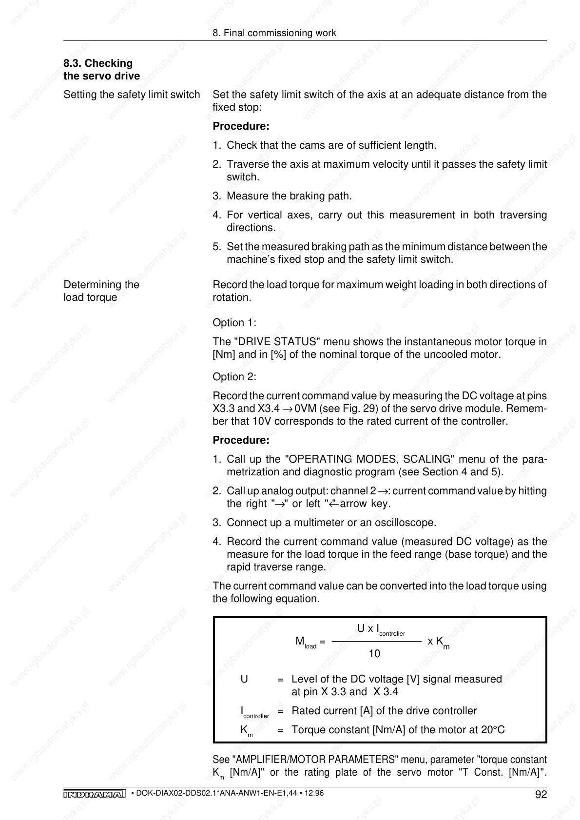
The current command value can be converted into the load torque using
the following equation.
U x I
controller
M
load
= ––––––––––––––– x K
m
10
U = Level of the DC voltage [V] signal measured
at pin X 3.3 and X 3.4
I
controller
= Rated current [A] of the drive controller
K
m
= Torque constant [Nm/A] of the motor at 20°C
See "AMPLIFIER/MOTOR PARAMETERS" menu, parameter "torque constant
K
m
[Nm/A]" or the rating plate of the servo motor "T Const. [Nm/A]
".
Determining the
load torque