• DOK-DIAX02-DDS02.1*ANA-ANW1-EN-E1,44 • 12.96
118
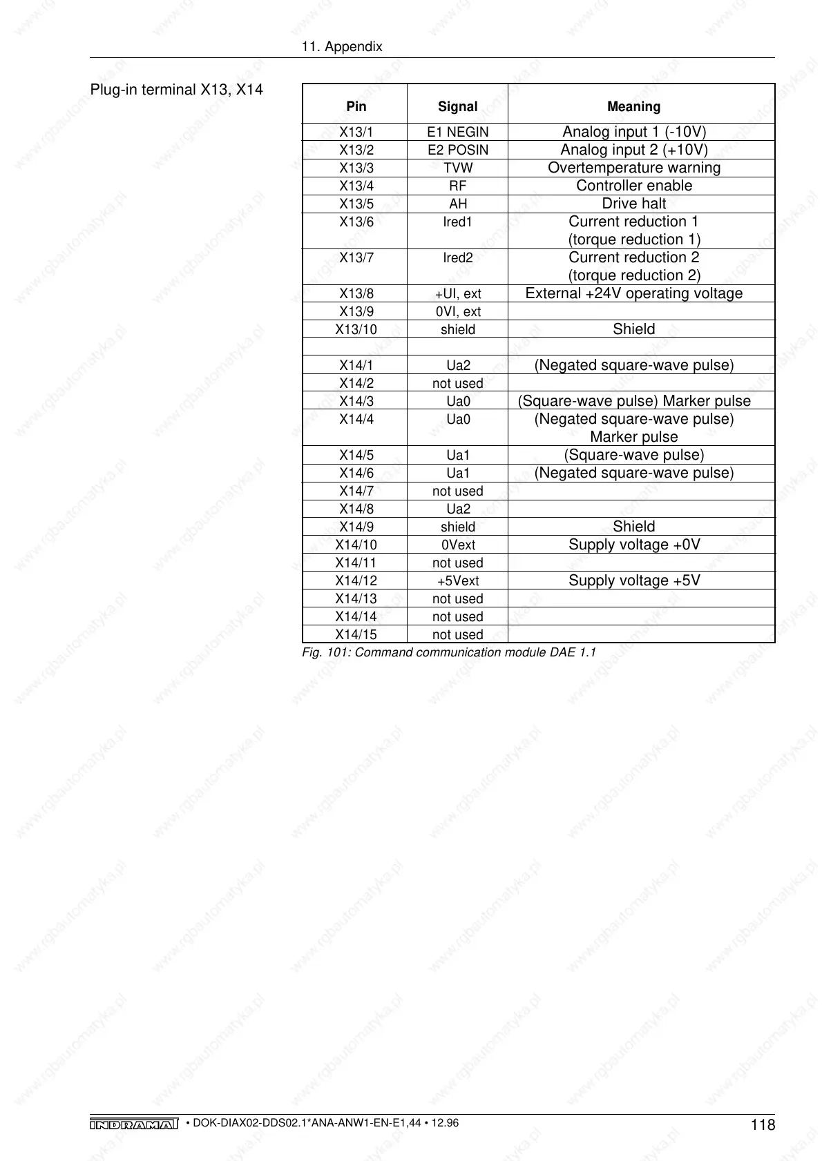
Pin Signal Meaning
X13/1 E1 NEGIN
Analog input 1 (-10V)
X13/2 E2 POSIN
Analog input 2 (+10V)
X13/3 TVW
Overtemperature warning
X13/4 RF
Controller enable
X13/5 AH
Drive halt
X13/6 Ired1
Current reduction 1
(torque reduction 1)
X13/7 Ired2
Current reduction 2
(torque reduction 2)
X13/8 +UI, ext
External +24V operating voltage
X13/9 0VI, ext
X13/10 shield
Shield
X14/1 Ua2
(Negated square-wave pulse)
X14/2 not used
X14/3 Ua0
(Square-wave pulse) Marker pulse
X14/4 Ua0
(Negated square-wave pulse)
Marker pulse
X14/5 Ua1
(Square-wave pulse)
X14/6 Ua1
(Negated square-wave pulse)
X14/7 not used
X14/8 Ua2
X14/9 shield
Shield
X14/10 0Vext
Supply voltage +0V
X14/11 not used
X14/12 +5Vext
Supply voltage +5V
X14/13 not used
X14/14 not used
X14/15 not used
11. Appendix
Fig. 101: Command communication module DAE 1.1
Plug-in terminal X13, X14