• DOK-DIAX02-DDS02.1*ANA-ANW1-EN-E1,44 • 12.96
84
7. Commissioning the functions of the digital AC servo drive
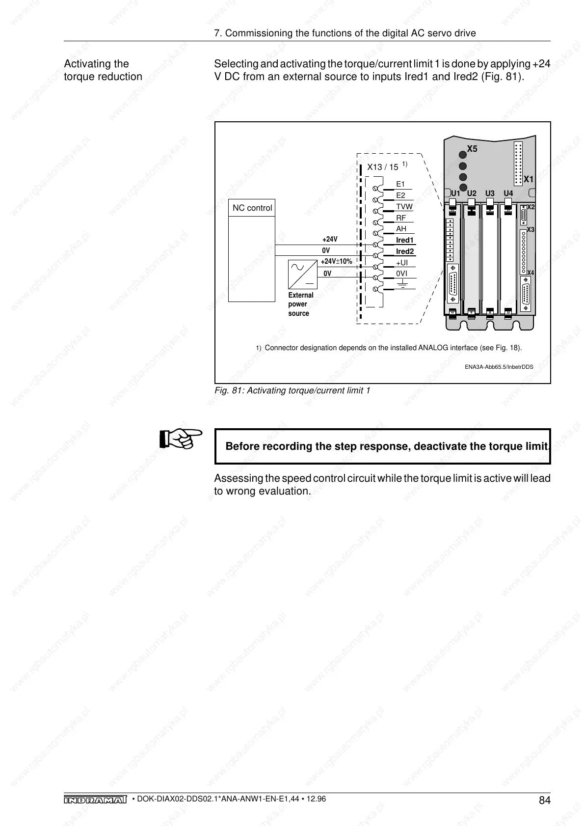
Activating the
torque reduction
Selecting and activating the torque/current limit 1 is done by applying +24
V DC from an external source to inputs Ired1 and Ired2 (Fig. 81).
Before recording the step response, deactivate the torque limit.
Assessing the speed control circuit while the torque limit is active will lead
to wrong evaluation.
Fig. 81: Activating torque/current limit 1
ENA3A-Abb65.5/InbetrDDS
E1
E2
TVW
RF
AH
Ired1
Ired2
+UI
0VI
X13 / 15
+24V±10%
External
power
source
0V
X4
X3
X5
U1
U3
U2
U4
X1
X2
1)
1)
Connector designation depends on the installed ANALOG interface (see Fig. 18).
NC control
+24V
0V