• DOK-DIAX02-DDS02.1*ANA-ANW1-EN-E1,44 • 12.96
59
7. Commissioning the functions of the digital AC servo drive
Errors causing drive-specific
error reactions
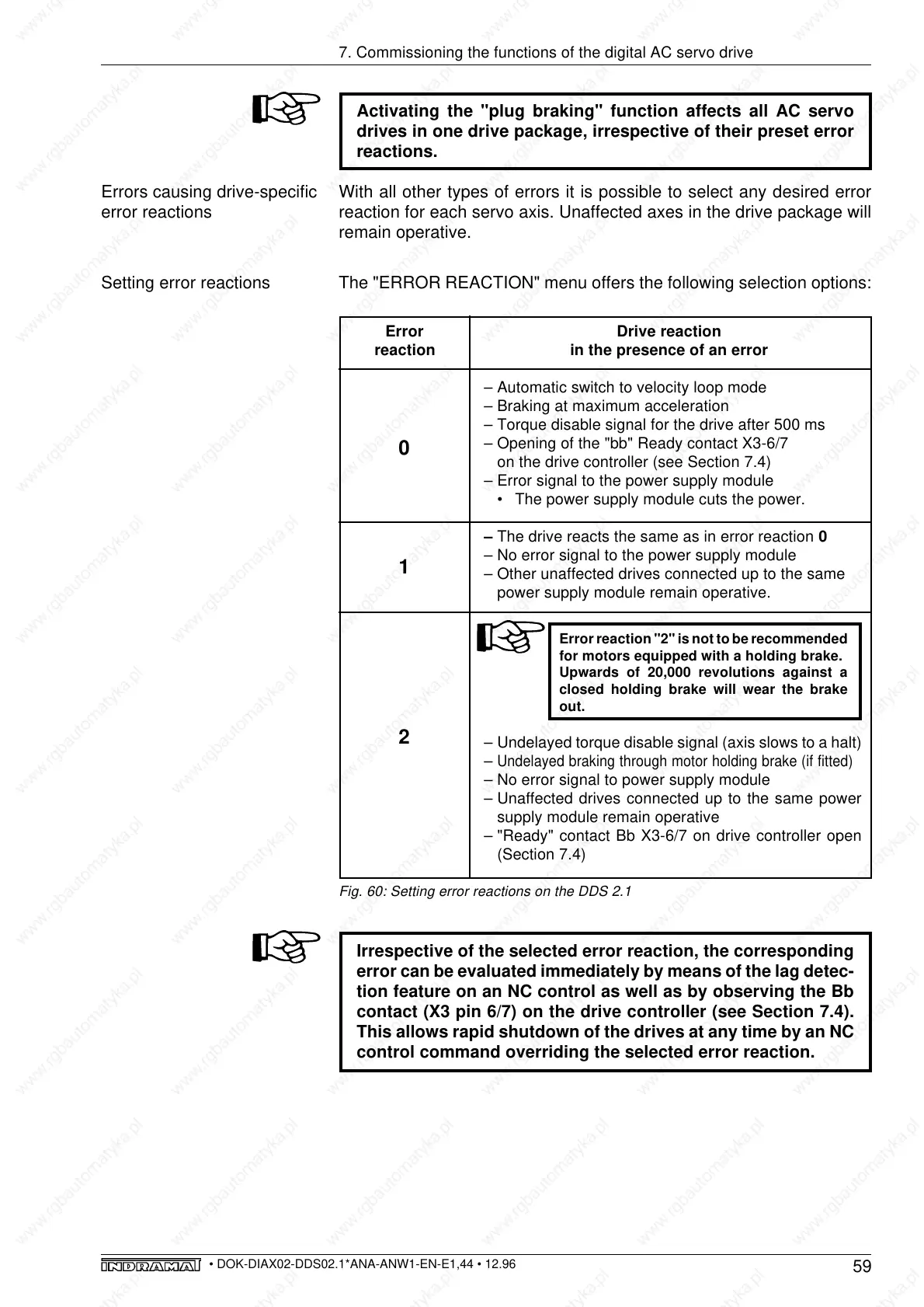
Setting error reactions
Error Drive reaction
reaction in the presence of an error
– Automatic switch to velocity loop mode
– Braking at maximum acceleration
– Torque disable signal for the drive after 500 ms
– Opening of the "bb" Ready contact X3-6/7
on the drive controller (see Section 7.4)
– Error signal to the power supply module
• The power supply module cuts the power.
– The drive reacts the same as in error reaction 0
– No error signal to the power supply module
– Other unaffected drives connected up to the same
power supply module remain operative.
Error reaction "2" is not to be recommended
for motors equipped with a holding brake.
Upwards of 20,000 revolutions against a
closed holding brake will wear the brake
out.
– Undelayed torque disable signal (axis slows to a halt)
–
Undelayed braking through motor holding brake (if fitted)
– No error signal to power supply module
– Unaffected drives connected up to the same power
supply module remain operative
– "Ready" contact Bb X3-6/7 on drive controller open
(Section 7.4)
0
1
2
Fig. 60: Setting error reactions on the DDS 2.1
Irrespective of the selected error reaction, the corresponding
error can be evaluated immediately by means of the lag detec-
tion feature on an NC control as well as by observing the Bb
contact (X3 pin 6/7) on the drive controller (see Section 7.4).
This allows rapid shutdown of the drives at any time by an NC
control command overriding the selected error reaction.
Activating the "plug braking" function affects all AC servo
drives in one drive package, irrespective of their preset error
reactions.
With all other types of errors it is possible to select any desired error
reaction for each servo axis. Unaffected axes in the drive package will
remain operative.
The "ERROR REACTION" menu offers the following selection options: