• DOK-DIAX02-DDS02.1*ANA-ANW1-EN-E1,44 • 12.96
69
7. Commissioning the functions of the digital AC servo drive
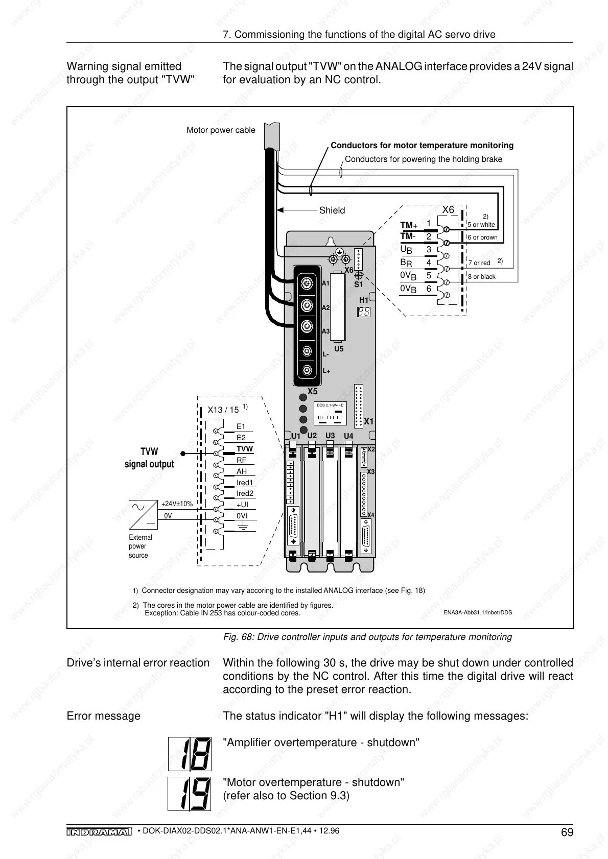
The signal output "TVW" on the ANALOG interface provides a 24V signal
for evaluation by an NC control.
Warning signal emitted
through the output "TVW"
Drive’s internal error reaction
Error message
Within the following 30 s, the drive may be shut down under controlled
conditions by the NC control. After this time the digital drive will react
according to the preset error reaction.
The status indicator "H1" will display the following messages:
"Amplifier overtemperature - shutdown"
"Motor overtemperature - shutdown"
(refer also to Section 9.3)
Fig. 68: Drive controller inputs and outputs for temperature monitoring
ENA3A-Abb31.1/InbetrDDS
E1
E2
TVW
RF
AH
Ired1
Ired2
+UI
0VI
X13 / 15
+24V±10%
External
power
source
0V
TVW
signal output
L-
L+
S1
A3
A1
A2
X4
X3
X6
X5
U5
U1
U3
U2
U4
H1
X1
X2
1
2
3
4
5
6
X6
Shield
Motor power cable
5 or white
6 or brown
TM+
TM-
U
B
B
R
0V
B
0V
B
7 or red
8 or black
1)
1)
Connector designation may vary accoring to the installed ANALOG interface (see Fig. 18)
2) The cores in the motor power cable are identified by figures.
Exception: Cable IN 253 has colour-coded cores.
Conductors for powering the holding brake
Conductors for motor temperature monitoring
2)
2)
DDS 2.1-W•••-D