• DOK-DIAX02-DDS02.1*ANA-ANW1-EN-E1,44 • 12.96
73
7. Commissioning the functions of the digital AC servo drive
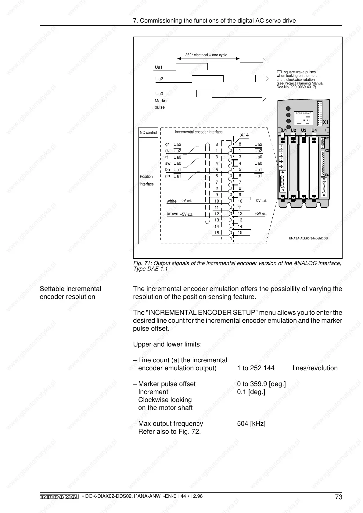
Fig. 71: Output signals of the incremental encoder version of the ANALOG interface,
Type DAE 1.1
The incremental encoder emulation offers the possibility of varying the
resolution of the position sensing feature.
The "INCREMENTAL ENCODER SETUP" menu allows you to enter the
desired line count for the incremental encoder emulation and the marker
pulse offset.
Upper and lower limits:
– Line count (at the incremental
encoder emulation output) 1 to 252 144 lines/revolution
– Marker pulse offset 0 to 359.9 [deg.]
Increment 0.1 [deg.]
Clockwise looking
on the motor shaft
– Max output frequency 504 [kHz]
Refer also to Fig. 72.
Settable incremental
encoder resolution
ENA3A-Abb65.3/InbetrDDS
Ua2
Ua2
Ua0
Ua0
Ua1
Ua1
X14
NC control
Position
interface
Incremental encoder interface
0V
ext.
X4
X3
U1
U3
U2
U4
X1
X2
360° electrical = one cycle
8
1
3
4
5
6
7
2
9
10
11
12
13
14
15
8
1
3
4
5
6
7
2
9
10
11
12
13
14
15
+5V
ext.
Ua2
Ua2
Ua0
Ua0
Ua1
Ua1
0V
ext.
+5V
ext.
gr
rs
rt
sw
bn
gn
white
brown
Ua2
Ua1
Ua0
TTL square-wave pulses
when looking on the motor
shaft, clockwise rotation
(see Project Planning Manual,
Doc.No. 209-0069-4317)
Marker
pulse
DDS 2.1-W•••-D