• DOK-DIAX02-DDS02.1*ANA-ANW1-EN-E1,44 • 12.96
81
7. Commissioning the functions of the digital AC servo drive
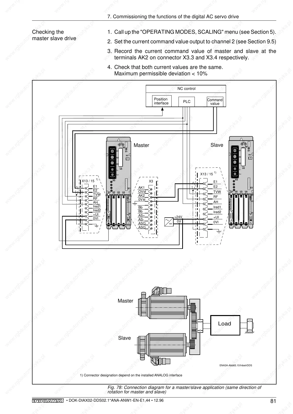
1. Call up the "OPERATING MODES, SCALING" menu (see Section 5).
2. Set the current command value output to channel 2 (see Section 9.5)
3. Record the current command value of master and slave at the
terminals AK2 on connector X3.3 and X3.4 respectively.
4. Check that both current values are the same.
Maximum permissible deviation < 10%
Checking the
master slave drive
Fig. 78: Connection diagram for a master/slave application (same direction of
rotation for master and slave)
ENA3A-Abb65.10/InbetrDDS
E1
E2
TVW
RF
AH
Ired1
Ired2
+UI
0VI
X13 / 15
L-
L+
S1
A3
A1
A2
X4
X3
X6
X5
U5
U1
U3
U2
U4
H1
X1
X2
AK1
OV
AK2
0V
Bb
Bb
AS+
AS-
ASQ
ASQ
X3
M
M
Master
L-
L+
S1
A3
A1
A2
X4
X3
X6
X5
U5
U1
U3
U2
U4
H1
X1
X2
Slave
E1
E2
TVW
RF
AH
Ired1
Ired2
+UI
0VI
X13 / 15
NC control
PLC
Position
interface
Command
value
Load
1)
1)
1) Connector designation depend on the installed ANALOG interface
+24V
0V
Master
Slave