Model WT3-201M Motorized Wire Crimp Pull Tester User’s Guide
3.1.4 Sample setup
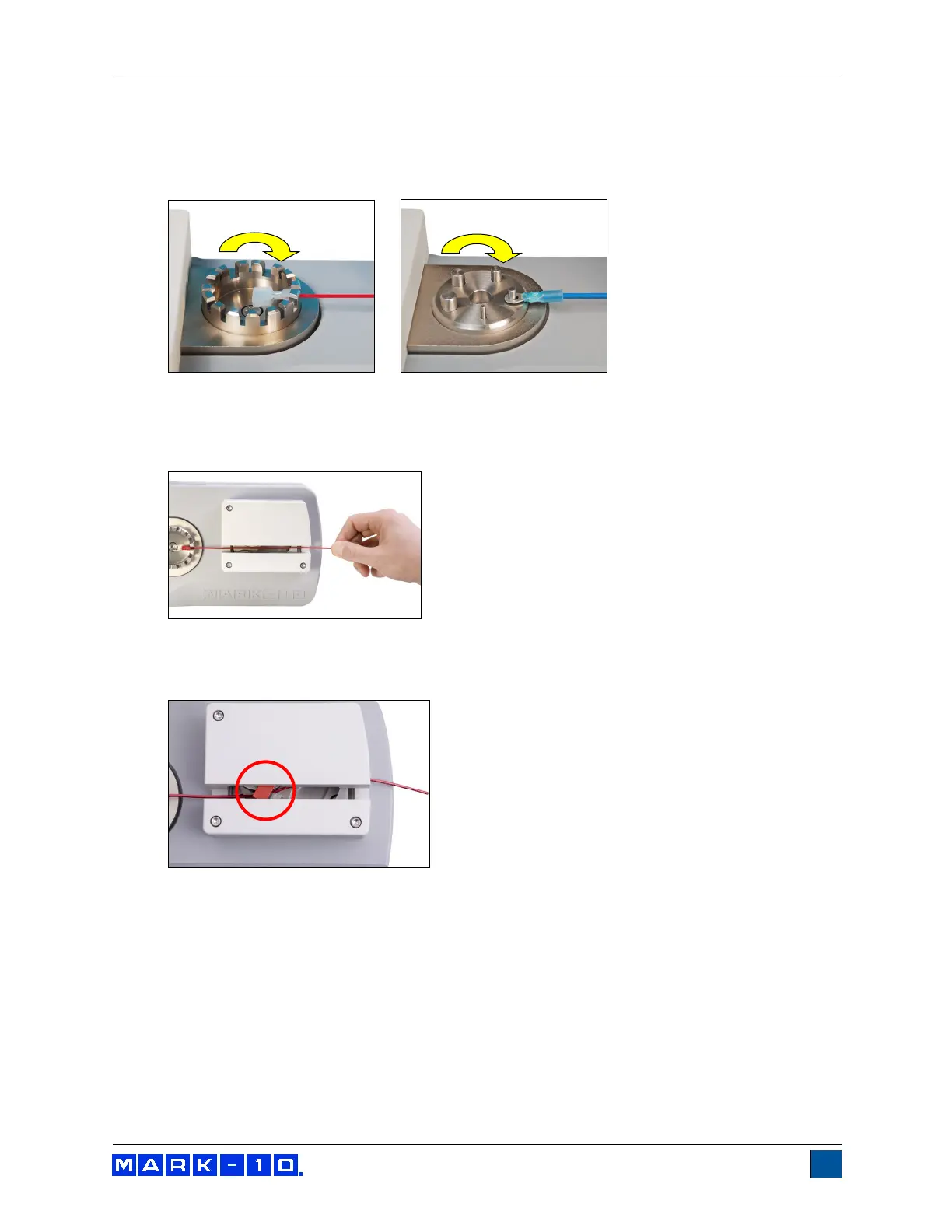
1. Secure the terminal into the standard terminal fixture or optional ring terminal fixture, as
shown in the images below. Rotate the fixtures until the desired slot or ring size is aligned with
the cam mechanism adjacent to the lever.
2. Insert the loose end of the wire between the cams in the mechanism. Keep the wire taut
as it is inserted. If auto-start is enabled, the test will begin when the switch is activated (refer to
later sections for operational details). Refer to the image below:
3. Note the protective red safety guard (circled, below), which automatically rotates into
position as the cam mechanism closes.