Model WT3-201M Motorized Wire Crimp Pull Tester User’s Guide
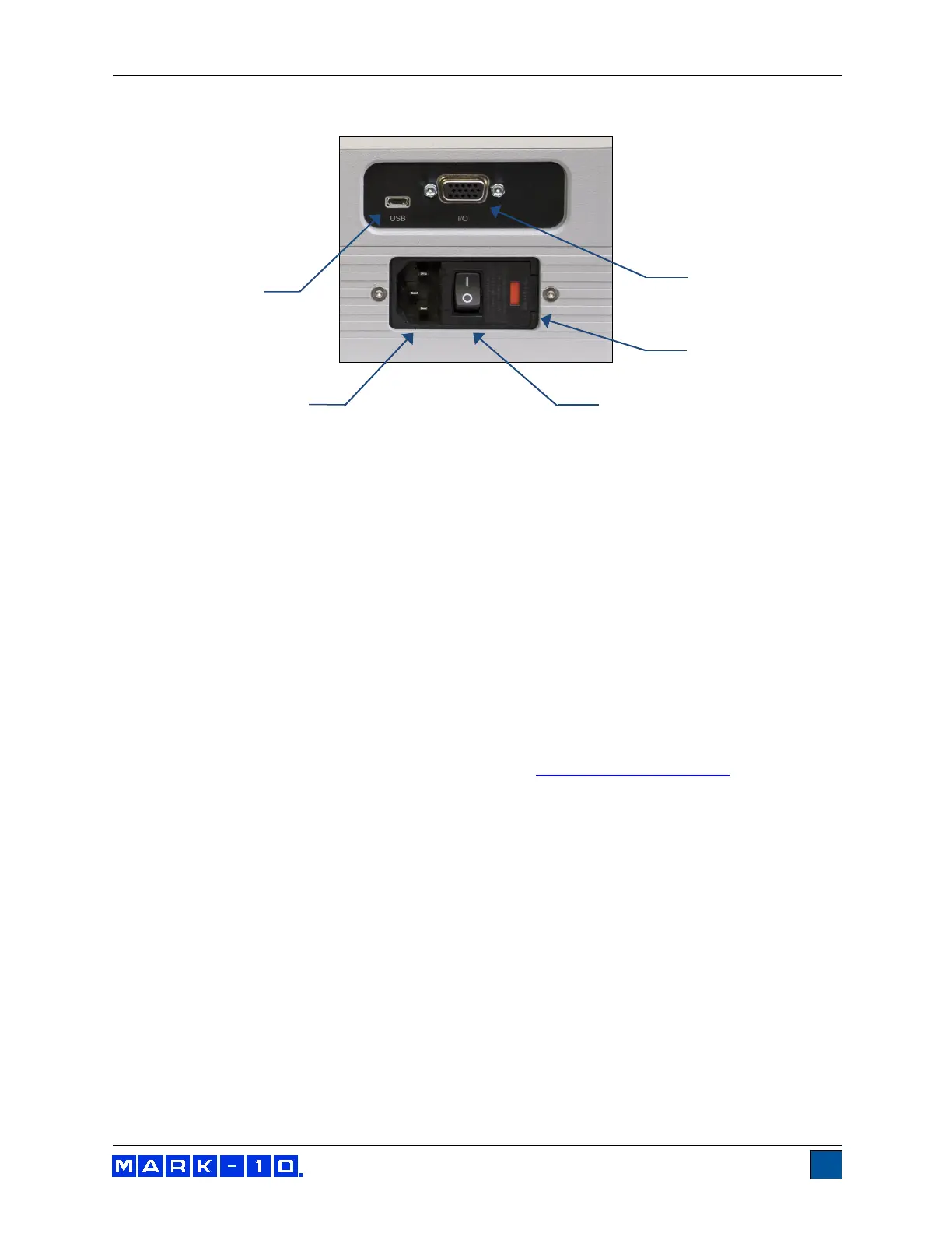
3.2 Connections and Outputs
1. I/O Connector
RS-232, set point, analog, Mitutoyo, and other outputs are provided. Refer to the
Communications and Outputs section for details.
2. Fuse
3. Power Switch
Use to turn power on and off.
4. Power Plug Receptacle
Plug the power cord in here. Refer to the Connecting power sub-section for important safety
information.
5. USB Connector
Plug the USB cable in here, for data output to a PC, PLC, printer, etc.
3.3 Installing the USB driver
If communicating via USB, install the USB driver available at:
www.mark-10.com/resources
Caution!
Install the USB driver before physically connecting the tester to a PC with the USB cable.
Further instructions for configuring and using the tester’s outputs are provided in the Communications
and Outputs section.