50
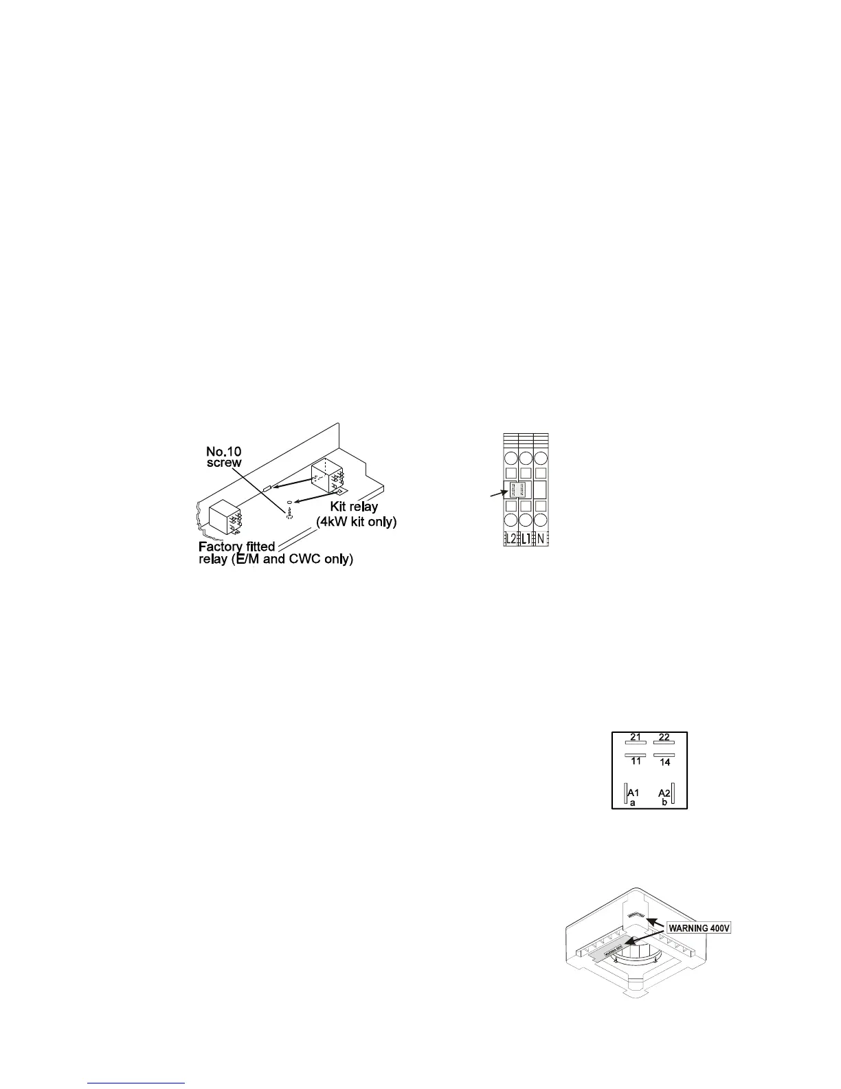
Fig. 3
Fig. 5
Fig. 4
1Ø link
plug
L2-L1
WIRING 1kW / 2kW / 3kW KITS
1. Connect the blue wire(s) from the heater element(s) to the in line connectors located on the inside of the coil in-
fill plate, opposite the factory fitted blue wire(s).
2. Connect the brown wire from the thermal fuse assembly to the in-line connector farthest from the base plate
opposite the brown wire with white boot.
3. Connect the yellow wire from the fuse assembly to the heater element, on the free terminal nearest the blue
protective device.
4. Tidy the wires with the cable ties provided.
RE-ASSEMBLY
1. Refit the chassis, fan cowl, internal electrics tray (and return air sensor and receiver pcba on ‘L’ and ‘E’ units).
2. ENSURE ALL FOAM BLANKING PIECES HAVE BEEN REMOVED FROM THE AIR-OFF SLOTS.
3. Reconnect the drain stub pipe(gravity drain units only)and drain hose.
4. Refit the fascia.
–o–o--O--o–o--
WIRING 4kW KITS
1. Connect two brown wires (from the cutout assy) and two blue wires (from the heater) to the in-line connectors on
the inside of the coil in-fill plate (brown opposite brown, blue opposite blue).
2. Connect the yellow wires from the fuse assembly to the heater elements, on the free terminals nearest the blue
protection devices.
3. Fit the kit relay to the internal electrics tray using the No.10 screw. (Fig. 3).
4. 1 Ph units: Connect the incoming Live supply to L1 and push the link plug hard home between L1 and L2 at the
external electrics box (Fig. 4).
3 Ph units: Connect one phase to L1 and another phase to L2. THE LINK PLUG MUST NOT BE FITTED.
–o–o--O--o–o--
4kW KIT: ELECTRO-MECHANICAL UNITS: RELAY WIRING
1. Remove the orange wire from the kit relay and discard.
2. Connect the single terminal ends of the kit wires to the kit relay just fitted:
Orange - relay terminal A1 (or a) (Fig. 5)
Blue - relay terminal A2 (or b)
3. Remove the orange and blue wires from the factory fitted relay. Connect to the piggy
back end of the orange and blue kit wires and reconnect to the factory fitted relay
in the original positions (Orange A1or a, Blue A2 or b).
4. Locate the loose black and brown wires on the internal electrics trays.
Remove the black insulating boots and connect to the kit relay.
Black - to 11 Brown - to 14.
5. Tidy the wires with the cable ties provided.
RE-ASSEMBLY
1. Refit the chassis, fan cowl, internal electrics tray.
2. ENSURE ALL FOAM BLANKING PIECES HAVE BEEN
REMOVED FROM THE AIR-OFF SLOTS.
3. Fit the two 400V warning labels (Fig. 6).
4. Reconnect the drain stub pipe(gravity drain units only)and drain hose.
5. Refit the fascia.
Fig. 6