67
SPECIFIC FAULT DIAGNOSIS FOR CC 875L UNITS
CONDITION POSSIBLE CAUSE ACTION
Check for alarms
i LEDs flashing - see table below
ii
If NO external connections are made to alarm terminal 5, the presence of an alarm condition can be tested for by checking for mains
voltage at terminal 5; full mains voltage = Alarm; less than mains voltage = Clear.
The outdoor unit can be caused to operate for test purposes by temporarily linking live directly to terminal 3
(up to 20 seconds delay)
L Outdoor unit runs continually at high Charge link still fitted Remove charge link
speed MHPUL in heating Normal
Minimum speed adjustment set too high Reset minimum speed
If all external devices test O.K. the outdoor unit pcb must be replaced
M No LED's lit or flashing
Unit commanded to be OFF Transmit 'ON'
No mains supply or internal fuse blown. (Fuse
F2 on internal control board blown during
configuring)
Check electrical supply and fuses
Fan motor plug disconnected Reconnect fan motor plug
Motor internal thermal protector operated Check motor and rectify
Cables to fascia not connected Reconnect
Circuit board fault Check circuit board and replace
High water level Check pump circuit (if fitted)
N All LED's lit, one flashing
Temperature sensor problem See table below
Resistor problem (non MHPUL) Check resistor connected
Outdoor sensor problem (MHPUL)
Replace outdoor unit sensor/check
interconnecting wiring
P
Indoor unit continues after stop/off
command
Overrun of 30 seconds in heating Normal
Q Unit will not respond to infrared
commands.
No audible answer signal
Battery discharged Replace battery
Handset corrupted Reset
R
Unit does not switch on/off at
intended times
Power cut has occurred
Send any command from the handset to
synchronise the timer
S
Unit not running in intended
mode/temperature
Power has been shut off for three or more
days, unit is exercising default programme
Use handset retransmit button
T
Fan does not run at the intended
speed
Heat Pumps Only
Fan runs at low speed until indoor coil is
warm, then changes to intended speed
U Short cycles between cool and heat System oversized for room Use cool or heat programmes NOT 'Auto'
V
First operation, room is overcooled
or overheated by 2°C
Set point temperature reverts to normal after
deadband is reached or 20 minutes of
operation
Normal
W Handset will not transmit
Heating commands Incorrectly configured - see page 23
Any commands Battery flat
X Compressor runs on Automatic minimum run time of 1.5 minutes Normal
HANDSET: If the handset fails to respond to button operations, disconnect and then reconnect the battery.
The previous programme state is retained in the memory.
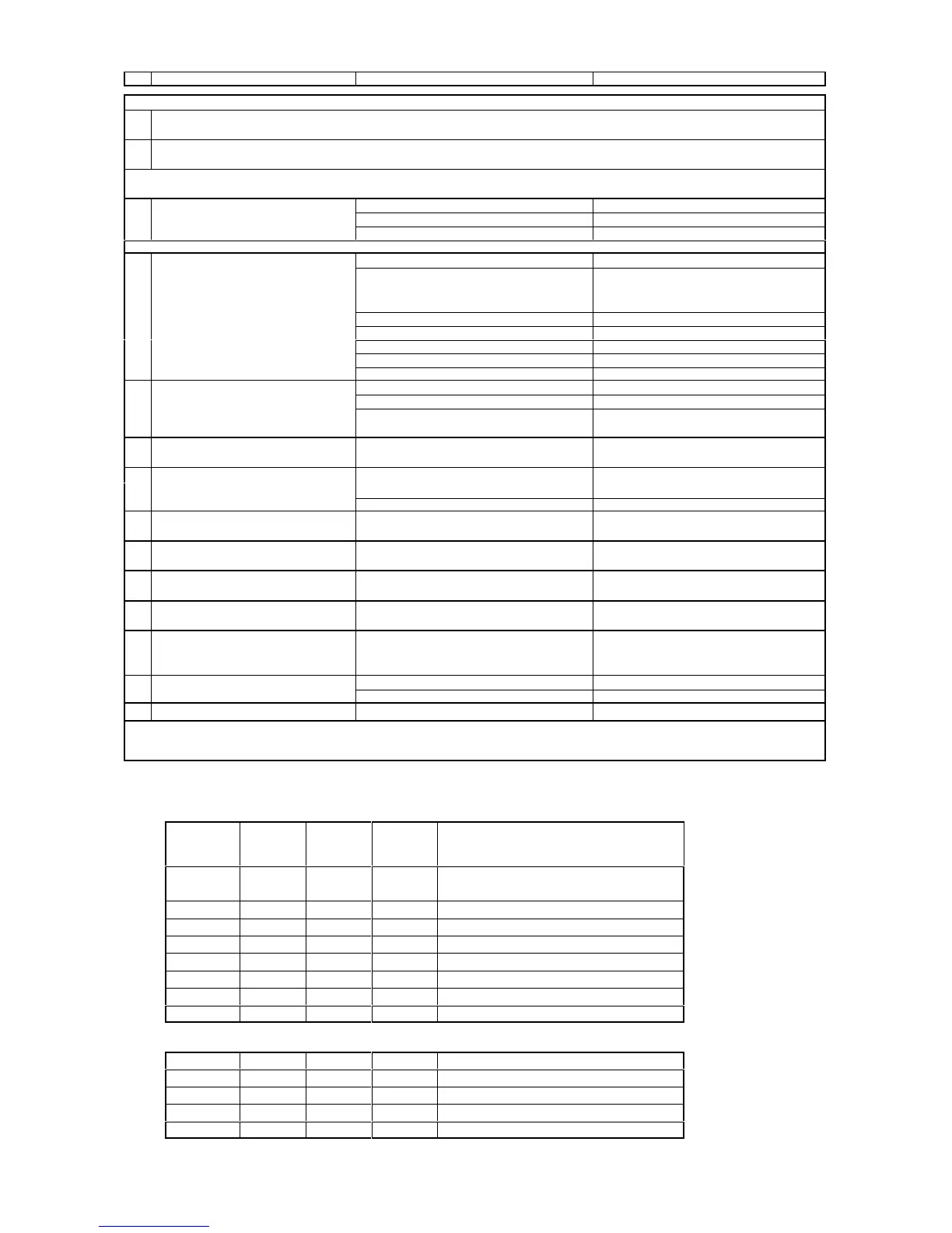
LED STATUS AND ALARM INDICATIONS
Status Displays
Cool Dry Fan Heat
DIAGNOSTICSD I4F
Green Red Red Amber
OFF OFF OFF OFF
No power, manual OFF, timed OFF, condensate
high level, fault in condensate control
ON OFF OFF OFF Cooling mode selected
ON OFF OFF BLINKS AUTO - predominantly cooling
OFF OFF OFF ON Heating mode selected
BLINKS OFF OFF ON AUTO - predominantly heating
OFF OFF ON OFF Fan mode selected
OFF ON OFF OFF Dry mode selected
OFF OFF OFF BLINKS Outdoor unit defrosting
Diagnostics
BLINKS x 4 OFF OFF OFF Room sensor missing
BLINKS x 4 OFF OFF OFF Indoor coil sensor missing
BLINKS x 4 BLINKS OFF OFF Outdoor coil sensor missing
BLINKS x 1 OFF BLINKS OFF Compressor overload
BLINKS x 2 OFF BLINKS OFF Pump fault