170
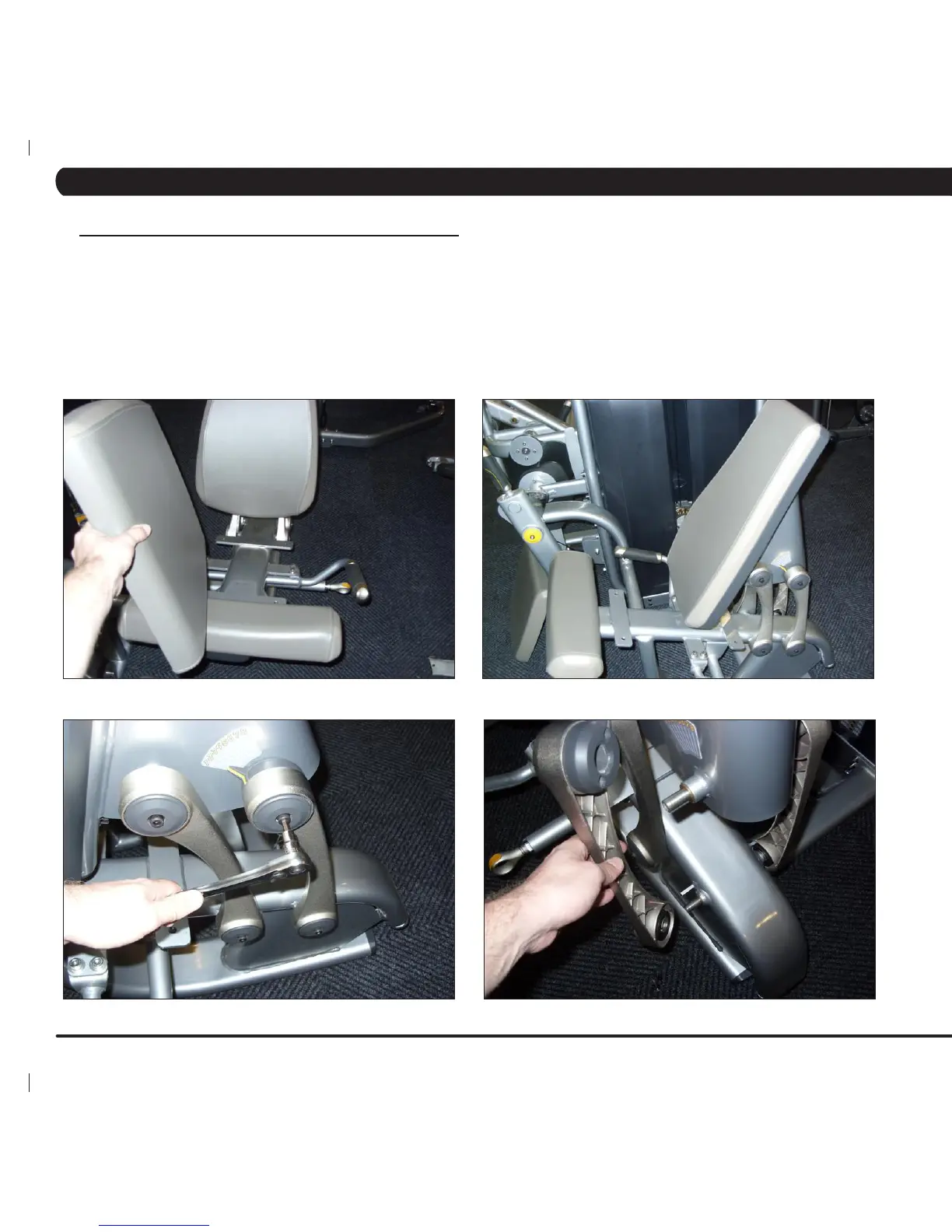
7.11 LARGE CONNECTING ROD REPLACEMENT
1) Remove the 4 screws holding on the seat pad and remove it (Figure A).
2) Move the back pad to the position furthest to the front of the unit - this will remove most of the tension on the connecting rod springs (Figure
B).
3) Remove the 2 screws holding on the connecting rod and remove it (Figures C & D).
4) Reverse Steps 1-3 to install a new connecting rod.
NOTE 1: When installing a new connecting rod, it will usually be necessary to remove the front connecting rod (Figure E) to install the rear one.
NOTE 2: When installing a new connecting rod, make sure that the swirl spring is present and properly installed (there should be at least 3 swirl
springs for each set of 4 large connecting rods) (Figures F & G).
NOTE 3: If replacing the right front connecting rod, be sure to re-install the ROM plate (Figure H).
FIGURE A
FIGURE B
FIGURE C
FIGURE D
CHAPTER 7: PART REPLACEMENT INSTRUCTIONS
 Loading...