Page 12 of 54 5100054 BND01O03.docx
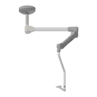
8.2.1. Canopy
The canopy covers the electrical connections routed through the carrier system. For this
reason, only qualified technicians are authorized to uninstall it.
8.2.2. Ceiling Column
Different ceiling column lengths compensate for different room heights, so that the system
is always positioned at working height.
The following ceiling column lengths are available:
• 200 mm
• 400 mm
• 800 mm
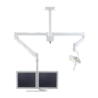
8.2.3. Extension Arm
The extension arm can be rotated through a maximum of 360° at axis A. The comfort
rotation end-stop can be adjusted towards both sides in 15 degree steps to avoid collisions
with walls or other components (Section 10.14, page 32).
The extension arm is equipped with four brake screws. They prevent the extension and
spring arm from drifting away. The brake force can be adjusted (Section 10.15, page 33
8.2.4. Spring Arm
The spring arm can be rotated through 360° at axis B with the rotation end-stop engaging
in its maximally folded position. It can be moved up and down between +45° and -70°.
The height end stop can be adjusted continuously between 0° and +45° (Section 10.13,
page 31).
The spring force is balancing out the weight of the injector and is preset to 18.5 kg. If the
payload varies from that amount the force needs to be adjusted.
A friction brake prevents an upward movement of the spring arm, when the injection liquid
is depleted. The friction brake exerts a force of ±1.5 kg.
8.2.5. Injector Column
The injector column provides a tablet to mount the CT Exprès® Injector safely. For a good
manipulation of the injector, a handle should be installed between tray and injector. Please
contact Bracco sales within the affiliate or legal agent in your country for more information.
The injector column can be rotated through 360° at axis C with the rotation end-stop
engaging in its maximally folded position.
8.2.6. Connection Plate
The connection plate provides an interface between the cables routed through the carrier
system and the cables from the cabinet. A strain relief feature is included as well.
8.2.7. Cables
The cables are preinstalled and routed through the extension arm:
• Power Cable 14 AWG with one WS-002 connector and ferrules
• Communication Cable with two 9 Pin D-Sub connectors