Page 24 of 54 5100054 BND01O03.docx
10.7. Installation of the Injector Holder
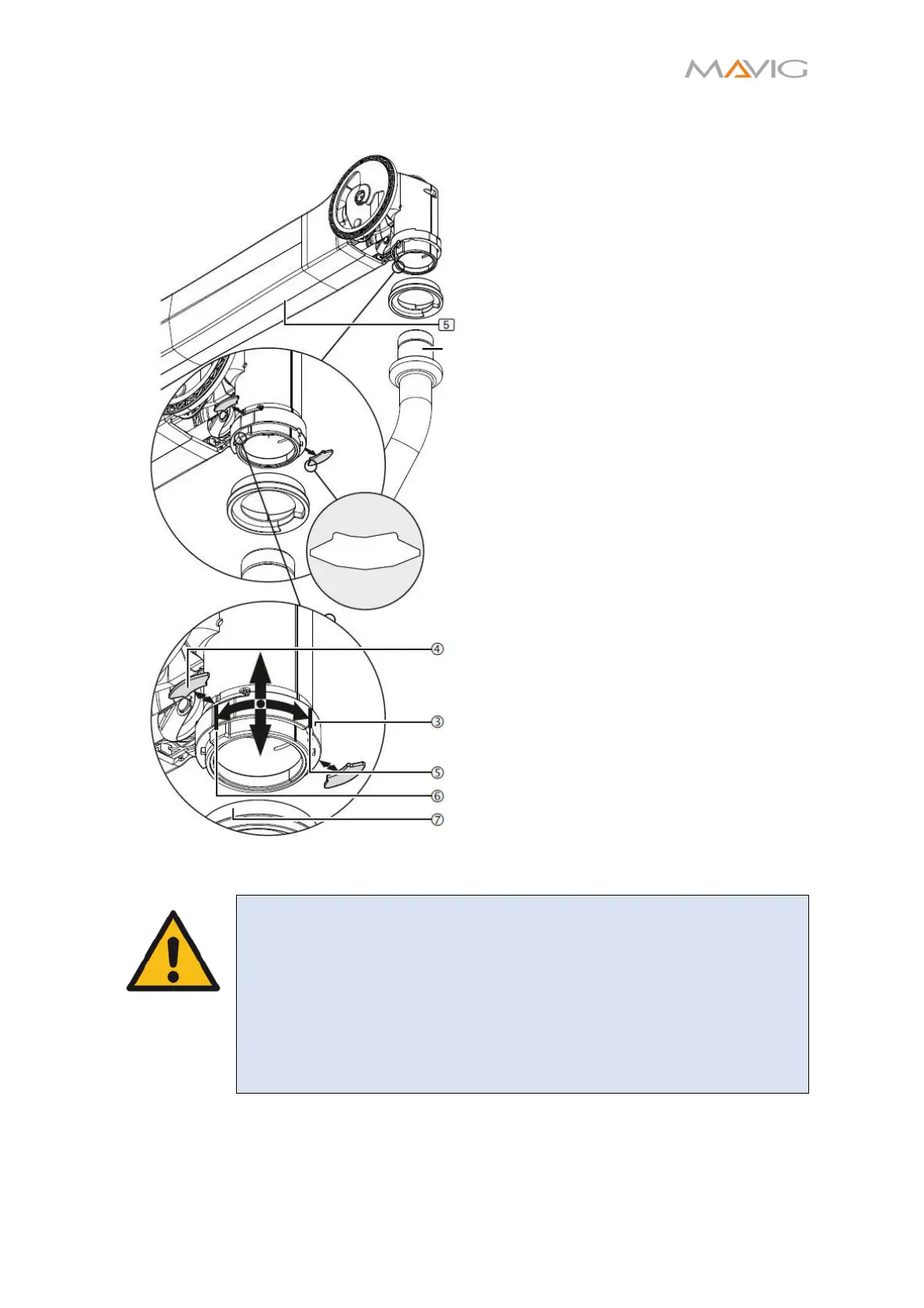
Figure 16 Installation of the Injector Holder
1. Loosen the brake screw, so it does
not block the insertion of the
Injector Holder. See Section
10.15.3.
2. Rotate the securing sleeve ③
approximately 90 degrees to the
right, route it slightly downwards
and then remove both opposite
securing elements ④ one after
another.
3. Make sure, that the securing
elements ④ and the injector
column spindle ⑧ are lubricated.
4. Insert the injector column rotation
end-stop ⑦ onto the spindle ⑧.
Make sure the lower rotation stop is
facing to the right as depicted in
Figure 16!
5. Insert the injector column spindle
⑧ into the spring arm up to the
end-stop. Avoid tilting it.
6. Push both securing elements ④
into the spring arm.
7. Rotate the securing sleeve ③
upwards and turn it approximately
90 degrees to the left.
• The cutout in the securing sleeve ③
must protrude over the brake screw
(not depicted).
8. Adjust the brake screws. See
Section 10.15.3.
9. Before mounting the covers adjust
the spring arm as described in
Sections 10.12 and 10.13.
WARNING – Falling parts.
Both Securing elements have to be properly mounted:
• No gap between the end-stop and the Spring Arm/Injector
Holder
• The Securing elements have to be inserted into the groove of
the spindle.
• Both latch pins have to snap into place audibly and be on the
same height after installation.