Page 22 of 54 5100054 BND01O03.docx
WARNING – Falling parts.
Check that all screws are properly tightened:
• Countersunk screw ISO 10642 M4x6
to 2 Nm
• Allen cylinder screw ISO 4762 M6x10
to 10 Nm
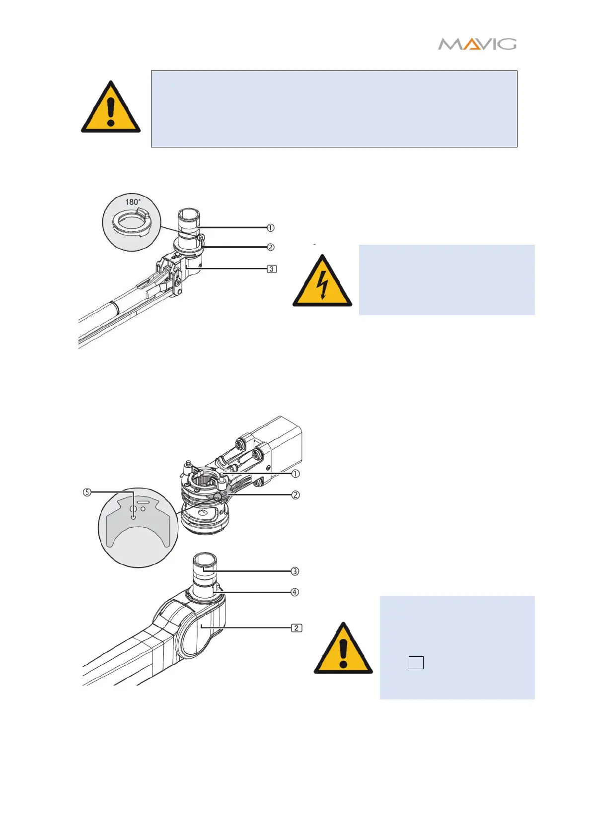
10.5. Installation of the Spring Arm
Figure 14 End-Stop between Spring Arm
and Extension Arm
1. Place the end-stop
onto the spring arm
spindle
.
• The single knob must face upwards and to the
rear end of the spring arm as depicted in
Figure 14.
WARNING – Electric Shock
Power cables can be twisted off
without a mounted end-stop!
1. Pull both latch pins
upward and both
securing elements
out of the
extension arm, until the latch pins snap
into the securing elements ⑤.
2. Insert the spring arm spindle ④ into the
extension arm up to the end-stop
without tilting.
3. Push both securing elements ② into the
extension arm until they snap into
place.
• Both securing elements ② must
protrude into the groove ③ on the
spring arm spindle ⑤.
• The latch pins
must audibly click into
place!
WARNING – Falling parts
If the securing elements ②
are not mounted properly
there is a risk of the spring
arm 2 with injector column
and injector dropping and
causing serious injuries