Page 28 of 54 5100054 BND01O03.docx
10.10. Installation of Connection Plate
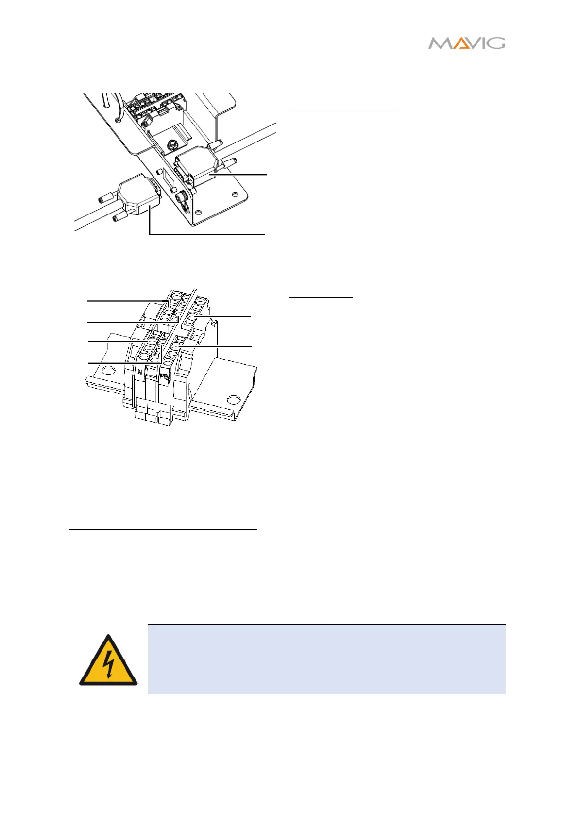
Figure 23 Attaching the communication
cables to the connection plate
Communication Cable:
1. Connect the communication cable routed
through the carrier system to the
connection plate. The connector is a male
D-Sub connector ①.
2. Connect the communication cable routed
from the control room to the connection
plate. The connector is a female D-Sub
connector ②.
Figure 24 Attaching the power cables to the
WAGO-clamp
Power Cable:
3. Route the power cable through the cable
tie.
4. Attach the three power cable wires of the
power cable P-NV at the WAGO-Clamp:
• Green/Yellow cable at position ① (PE)
• Brown cable at position ②
• Blue cable at position ③ (N)
5. Route the power cable provided by the
hospital through the opposite cable tie
6. Attach the wires accordingly at the
positions ④, ⑤ and ⑥.
7. Tighten the cable ties to provide a stress
relief.
Fixating the Connection Plate in place:
The connection plate has to be fixed in place to avoid movement and damage to the cables.
As every installation site is different it is the installation technician’s responsibility to find
the best solution.
The connection plate offers several options to fix it in place. The provided holes can be
used to screw it to the ceiling, to tie it to a strut or the ceiling column with some cable ties.
The method used depends on the available space and possibilities at the installation site.
WARNING – Electric Shock
Care must be taken, that the cables are not bent too much, so that they
are not damaged!
④
①
②
③
⑤
⑥
②
①