Page 18 of 54 5100054 BND01O03.docx
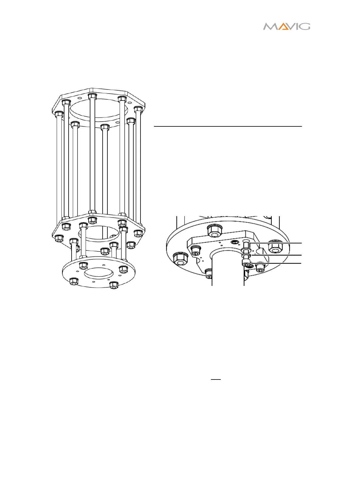
10.2. Substructure TS1524 (optional)
MAVIG can provide the substructure TS1524, if desired.
Figure 8 Substructure TS1524
• Adaptable length between 100 and 626 mm
• Total Weight of 22 kg
• Certified for more weight and momentum than
necessary for the Bracco CT Exprès® Carrier
System
Installation of the Ceiling Column to the TS1524:
1. Place the DIN 127 M10 snap ring ② and the
subsequent DIN 125-A M10 washer ① on the
DIN912 M10x40 screw ③ as displayed in
Figure 9 (part of the TS1524 accessory kit).
2. Apply Loctite® 270 on each screw and install
them with a torque of 50 Nm (±3%).
3. Apply paint seal on each tightened screw.
Further details can be found in installation
instructions DBF02Oxx.
Figure 9 Installation of the Ceiling Column to the
Substructure
10.3. Installation of Ceiling Column
Prior to installation the ceiling must be checked by a structural engineer and the installation
must occur under the guidance of the respective construction supervision!
The determination of the individual fastening elements and their respective tightening
torques for mounting on ceiling and wall is the sole responsibility of the respective
structural engineer.
The screws used to attach the system to the ceiling are not part of the system!
The maximum pull-out force and momentums for the ceiling anchors shall be calculated in
accordance with local building codes and it is part of a structural analysis done by the
customer. The necessary information is provided below (see Figure 10, Table 1, Figure 11).
①
②
③