Page 26 of 54 5100054 BND01O03.docx
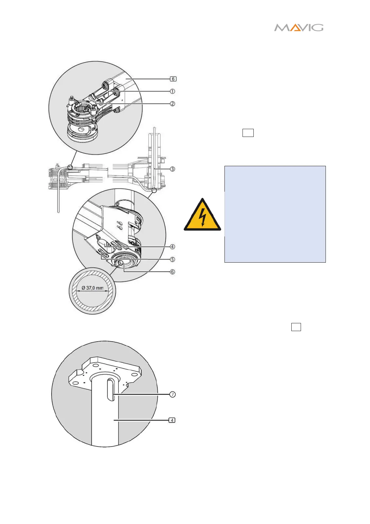
10.9. Cable Routing
Figure 19 Cable Routing in the Extension
Arm
Figure 20 Cable Routing in the Ceiling
Column
• Ceiling column, extension arm, spring
arm and injector column have to be
installed according to Sections 10.1,
10.4, 10.5 and 10.6.
• All covers have to be disassembled
according to Sections 10.16, 10.17 and
10.18.
• The cables ③ are pre routed through the
extension arm 6 and should protrude
out of the front ①/④ and rear cable
apertures
after installation of the
extension arm according to Section 10.4.
WARNING – Electric Shock
Damaged cables can energize
the carrier system:
• The cables ③ must lay
next to each other without
crossing themselves.
• The cables ③ must not be
twisted.
• The cable insulations must
be undamaged.
1. Route the cables
at the front through
the cable aperture downward to the
spring arm.
• Start with the cable with the largest
cable plug.
2. Route the cables into the aperture ⑥ and
③ through the ceiling column 4 to the
aperture ⑦.
• Make sure the cables are secured at
the cable fixing devices ②/⑤.
• Check that the external cables ③ are
not exposed to tensile stress in any
possible position and that the
extension arm can be freely moved.