Page 35 of 54 5100054 BND01O03.docx
10.17. Installation/Disassembly of Socket Covers
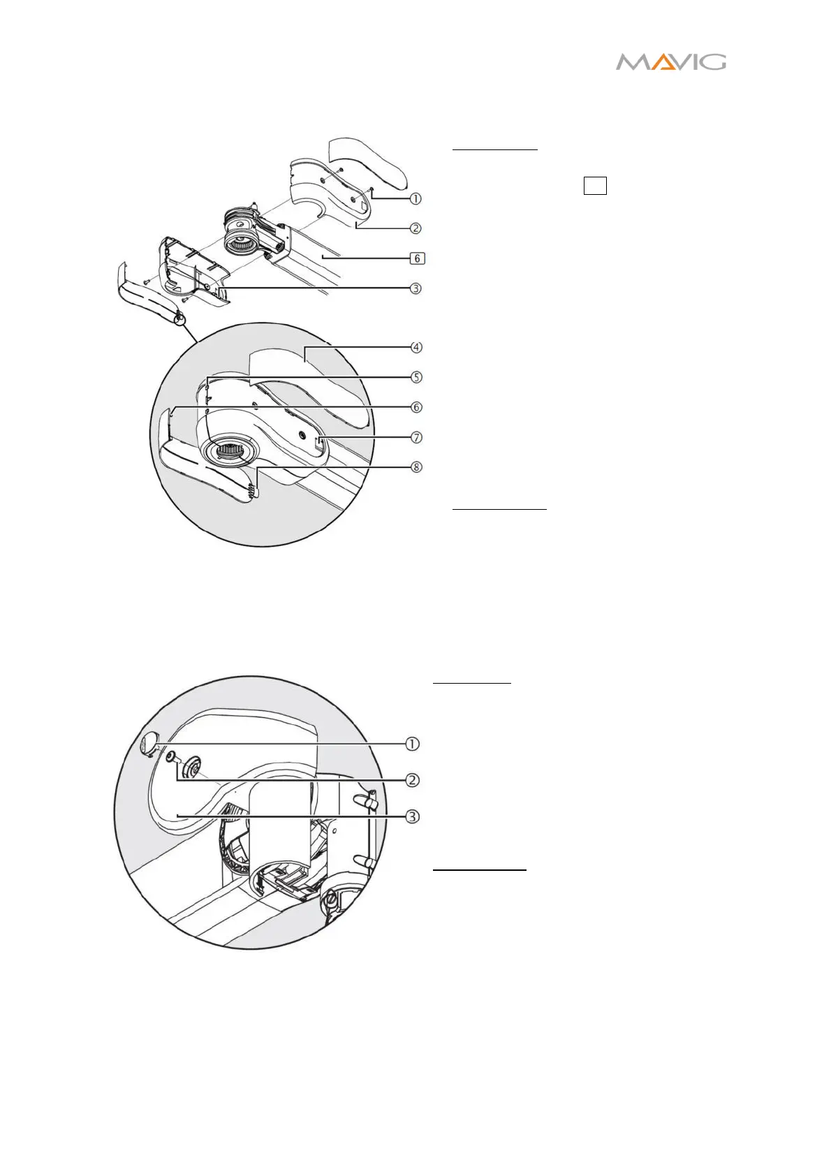
Figure 36 Mounting of the Socket Covers
Installation:
1. Screw the socket cover
onto the
extension arm 6 with two cross-
recessed head screws M4x10 ①
(Torx T10).
2. Place the second socket cover ② in
a way, that the locking pins ③ are
interlocking and screw in two cross-
recessed head screws M4x10 ①
(Torx T10).
3. Insert the latches ⑥ of the
decorative covers into the fittings
⑤.
4. Insert the straps ⑧ into the pockets
⑦ by bending the decorative cover
slightly. Make sure the latches ⑥
stay the fittings ⑤.
5. Make sure the decorative covers ④
sit tightly in place and there are no
gaps between the covers.
Disassembly:
To disassemble the covers follow the
instructions in reverse order.
10.18. Installation/Disassembly of Spring Arm Covers
10.18.1. Front Spring Arm Cover Panels
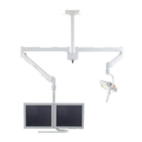
Figure 37 Front Spring Arm Cover Panels
Installation
1. Place both front cover panels
at
the spring arm and carefully engage
the latches.
2. Secure each front cover panel with
a cross-recessed head screw M4x10
– 10.9 screw ②(Torx T10).
3. Insert a PUSH button ① on each
side such that it is flush with the
cover panels.
Disassembly:
1. Firmly press on the PUSH button ①
and remove it by pulling at the
emerging gap.
2. Unscrew the cross-recessed head
screw M4x10 – 10.9 screws ②(Torx
T10).
3. Carefully disengage the latches of
both front cover panels.
4. Take off both front cover panels
.