Page 44 of 54 5100054 BND01O03.docx
• The cutout
in the securing sleeve
must protrude over the brake screw
.
10. Check, that the securing element
is securely in place and the injector column
rotates freely.
Checking the second securing element
11. Dismantle, check and remount the second securing element according to steps 3
to 10.
Adjusting the height stop point
12. Adjust the height stop point back to its original position according to Section
10.13, page 31.
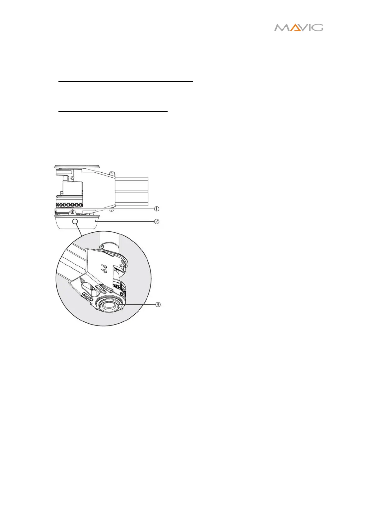
11.4. Checking the Securing Ring at Axis A.
Figure 42 Checking the Securing Ring
1. Disassemble the covers according to Section
10.16, page 34.
2. Remove the bottom cover panel ②:
• Unscrew the three cross recessed head
screws M4x10 ① with a Torx T10
screwdriver.
• Carefully remove the bottom cover panel
②.
3. Check the securing ring ③ between the upper
extension arm and the ceiling column spindle:
• The securing ring ③ must be undamaged
and sealed!
4. Install the covers according to Section 10.16,
page 34.