28000 12MXT
M1 77
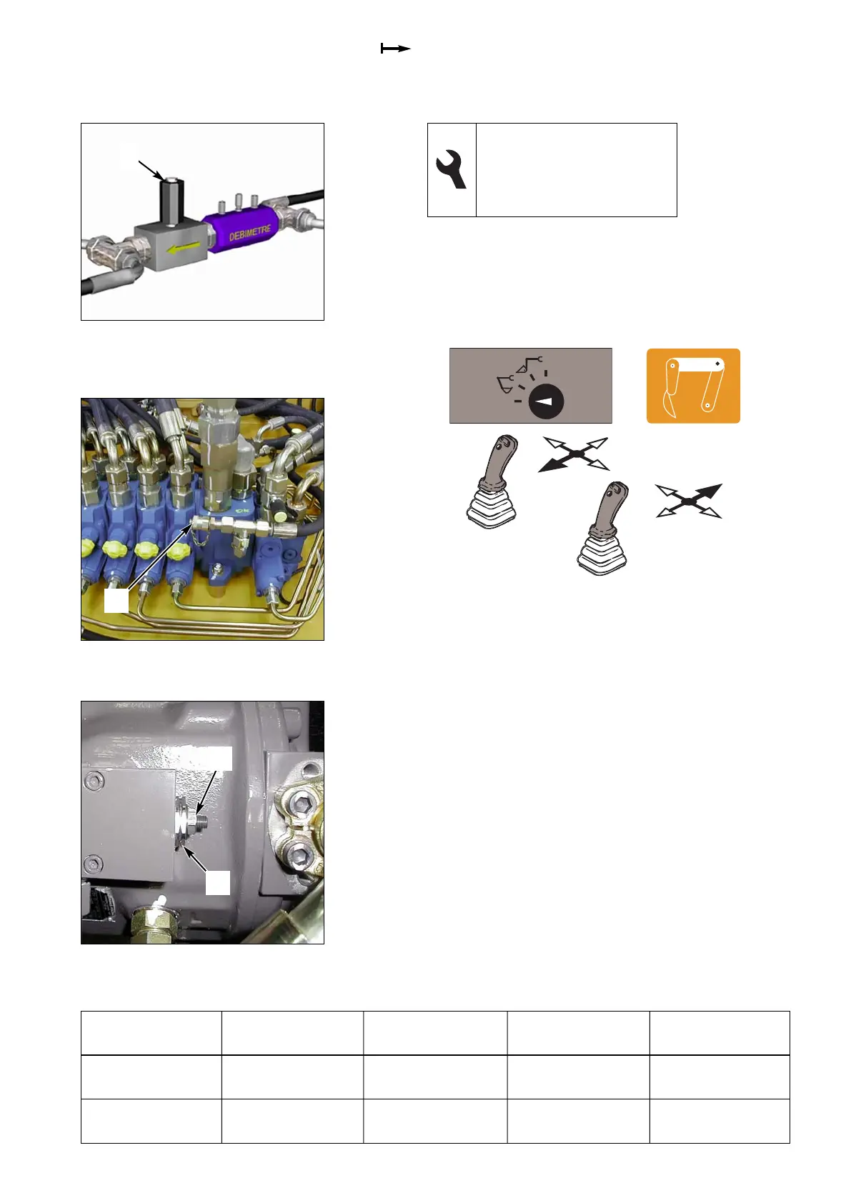
Fig. 3 Equipment pump
Fig. 2 SX14 valve block
Fig. 1 Flow meter adaptation kit
(TOP-TEST MX)
1
1
2
1
14.4.7 Adjusting the power regulation
1- Put the selector switch on “MECALAC 1”, pull the left
manipulator back, push the right manipulator forward
(as far as it will go) to allow the oil to circulate (small
chambers of the dipper ram and intermediate boom
ram).
2- Accelerate the engine to maximum regime.
3- Reduce the flow (115 l/min) using the tap on the flow
meter (1 fig. 1).
4- Measure the pressure (1 fig. 2) using the manometer.
5- Loosen the lock nut and turn the pressure controller
screw (1 fig. 3) clockwise to increase the pressure.
6- Reduce the flow (87 l/min) using the tap on the flow
meter (1 fig. 1).
7- Measure the pressure (1 fig. 2) using the manometer.
8- Loosen the lock nut and turn the pressure controller
screw (2 fig. 3) clockwise to increase the pressure.
9- Check that the regime of the engine does not exceed
2,000 rpm.
13 and 27 flat spanners
3 male hexagonal spanner
Inductive sensor
Manometer, 0 - 600 bar
Flow meter adaptation kit
Operation
Pressure
(bar)
Speed
(rpm)
Measurement
(ref. no.)
Adjustment
(ref. no.)
Power regulation
at 115 l/min
220 (+10 -10) > 2,000 1 fig. 2 1 fig. 3
Power regulation
at 87 l/min
265 (+10 -10) > 2,000 1 fig. 2 2 fig. 3