15
DAR = 60 second value/30 second value
During all insulation tests the symbol will flash indicating that a test voltage is present.
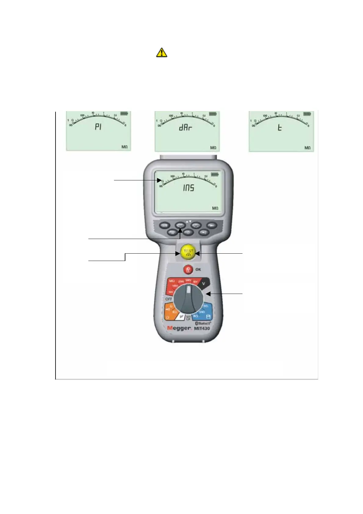
(a) Insulation resistance testing – timed procedure (not MIT400, MIT405 or MIT480).
(Refer to Figures 7)
1. Connect the test probes to the isolated circuit under test.
2. Turn the instrument ‘O
by rotating the selector switch to the required test voltage
position either 50 V, 100 V, 250 V, 500 V or 1 kV.
3. Select the timed test (t) by pressing ‘PI/DAR/t’ function button repetitively until the
desired function is displayed.
Note: the test type defaults to insulation resistance when the range switch is moved.
See figure 7 screens B, C & D.
Figure 7 Insulation resistance – timed modes
Screen B
Indicatin
a PI test
Screen C
Indicatin
DAR test
Screen D
Indicatin
timed test
Screen A
(Indicating insulation
test mode)
Step 1:
Connect test leads to
circuit
Step 3:
PI, DAR, t or INS
Step 6:
Press TEST to abort if
required
Step 4:
Press TEST and hold
Step 2:
Range selection
www.GlobalTestSupply.com
Find Quality Products Online at: sales@GlobalTestSupply.com
 Loading...