56 of 289
• If the x-cable is not positioned within the large cut-out on the right side of the x-cable tension
gauge as shown in the image, the tension is out of specication and needs adjustment.
a. Remove, but do not discard, the side cover support foam.
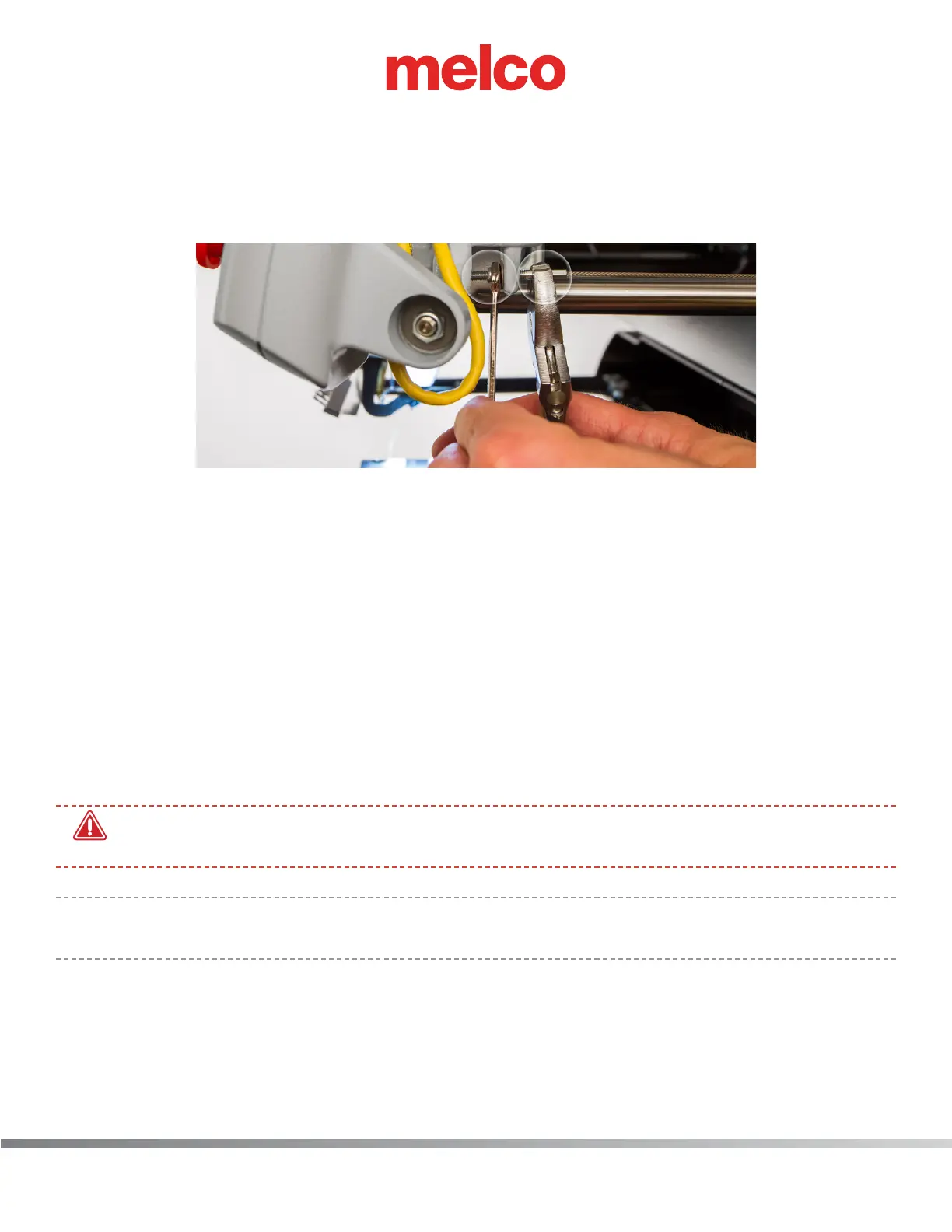
b. Locate the M4 nut and the x-cable tension stud and the end of the x-cable where it
mounts to the front of the upper arm as shown in the image.
c. Using a 7mm wrench, grip the M4 nut and with a pair of pliers or adjustable wrench, grip
the x-cable stud at the end of the x-cable as shown in the image.
d. To increase tension, rotate the M4 nut with the wrench counter clockwise while holding
the x-cable stud with the pliers or adjustable wrench.
e. When the x-cable is roughly at the lower edge of the cut-out on the right side of the ten-
sion gauge, remove the wrench, pliers and the tension gauge.
f. Remove the tools and the x-cable tension gauge before proceeding.
g. Move the X-Beam full travel to the front and back and the X-Carriage full travel left and
right a few times to ensure proper settling of the X-Cable tension.
h. Test the tension again.
25. Remove the x-cable tension gauge before proceeding.
•
WARNING!! If you proceed without removing the x-cable tension gauge, damage to your ma-
chine will occur and a service call will be necessary.
•
Note: will not be responsible for any damage to the machine or related service costs caused by
not removing the tension gauge.
26. Position the right side cover in its original location on the machine as shown in the image.