84 of 289
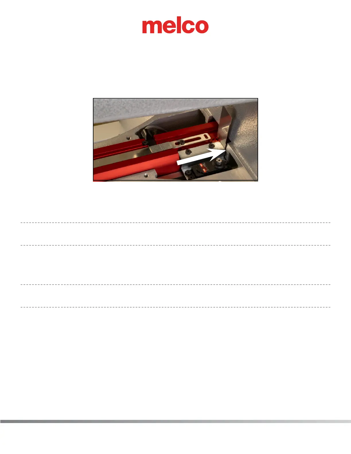
11. Install the new bracket assembly to the lower arm extrusion assembly using two (2) M3 low head
screws.
• Using gauge PN 00927-01 (supplied in the operator’s kit), place gauge at the rear of the cut
out in the lower arm extrusion (as shown below). Slide the new motor bracket assembly back
until it makes contact with the gauge. This will create the appropriate gap of 0.5mm.
• Tighten the screws.
12. On the trimmer PCBA locate the connection labeled K4 (bottom connector) and connect the cor-
responding harness.
13. Plug in the power cord, open the Melco OS and power the machine on.
•
A selector timeout error will appear when the machine is powered on. Simply close the error
message.
14. In the Melco OS under Tools> Maintenance>Steppers tab, click the [Select] Button, then click the
[Cut] button. Now click the [Select] button again, and then click the [Home] button. This will en-
sure the home position for the motor is set correctly.
•
Please note: The buttons will not change color as the connecting link is not currently connected
to the motor drive arm and so is not triggering the sensor.
 Loading...
