10 D33451 | Date 01/2018
Construction and description
2. Construction and description
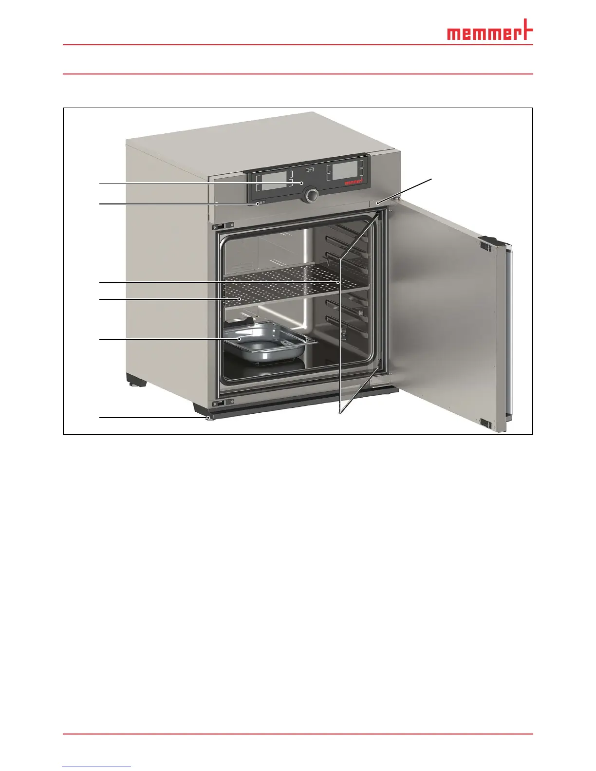
2.1 Construction
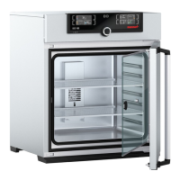
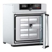
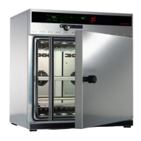
1
2
3
4
5
6
7
Fig. 2 Construction of CO
2
incubators ICO
1 ControlCOCKPIT with capacitive function
keys and LCD displays (see page 26)
2 On/Off switch (see page 22)
3 Inner glass door
4 Stainless steel perforated sheet
5 Water tray (passive humidity control)
6 Adjustable feet
7 Nameplate (see page 12)
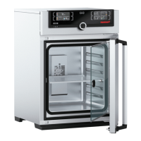
2.2 Description and function
Air is heated inside the appliance by means of large-area all-round heating.
The interior of appliances with passive humidity control is humidified with water that evapo-
rates from a tray that is placed inside. The interior of appliances with active humidity control
is humidified with water evaporating at a set rate from a tank by means of a hot-air generator
on the rear side of the appliance. The sterile hot air is introduced into the interior above the
fan and mixed with the air current. In appliances with water trays, a Peltier humidity trap in
the back of the appliance limits humidity. Appliances with active humidity are dehumidified
with a dosed supply of fresh air provided through a sterile filter.
Carbon dioxide (CO
2
) and nitrogen (N
2
only for models with O
2
module) are also injected into
the interior through sterile filters. Interior ventilation ensures a uniform distribution of the
gases, creating a homogeneous atmosphere. The oxygen concentration is controlled by intro-
ducing nitrogen: If nitrogen is introduced, the concentration of oxygen decreases.