38 D33451 | Date 01/2018
Operation and control
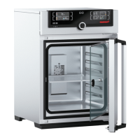
6. By turning the turn control, adjust the
desired upper alarm limit, in the example
on the right 15 %.
ALARM
min
7.0%
max
15.0%
7. Accept the selection by pressing the
confirmation key and leave the
Alarm
display by pressing the activation key on
the side. CO
2
monitoring is now active.
ALARM
min
7.0%
max
15.0%
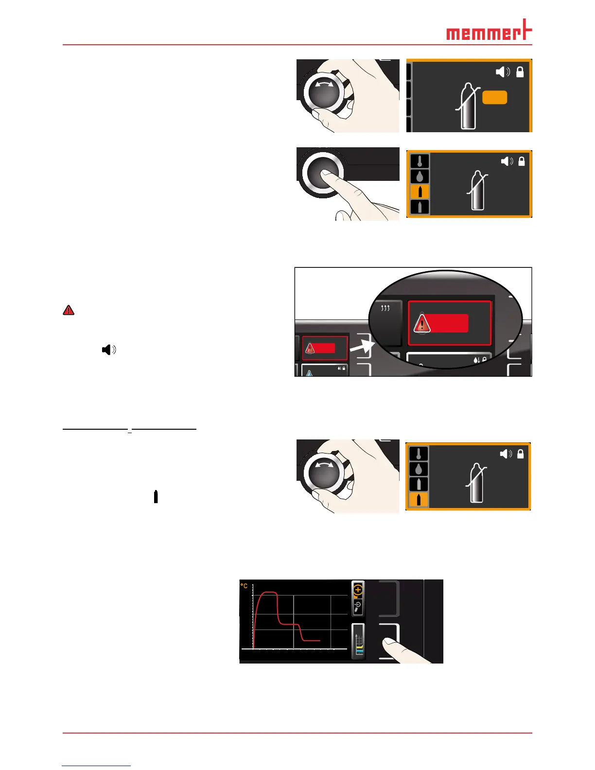
5.6.4 O
2
monitoring
(only for appliances in the corresponding configuration)
If O
2
monitoring was triggered, this is
indicated by the O
2
display: the actual value
is highlighted in red and a warning symbol
is shown ( Fig. 23 ). If the acoustic alarm
has been activated in menu mode (
Sound,
see page 59, as indicated by the speaker
symbol
), the alarm is additionally
signalled by an intermittent acoustic signal.
Information on what to do in this case is
provided in chapter Malfunctions, warning
and error messages from page 41.
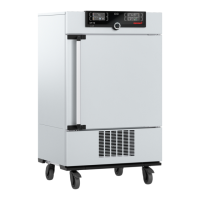
Adjusting O
2
monitoring
O
2
monitoring is set the same way as CO
2
monitoring (see page 37). After the alarm
display is activated, turn the turn control un-
til the O
2
adjustment entry is selected (upper
gas bottle symbol
) and set the min and max
values as described above.
ALARM
min
10.0%
max
10.0%
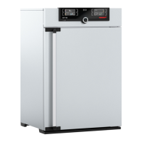
5.7 Graph
The GRAPH display provides an overview of the chronological sequence of the setpoint values
and actual values for temperature, humidity, CO
2
and O
2
content as a curve.
Press the activation key to the
right of the
GRAPH display. The
display is enlarged and the tem-
perature profile shown.
0 4 8 12162024
°C
40
20
60
80
100
Fr 20.10.2010 20:34
12.09.2012
14.00 16.00 18.00
38
39
40
FEUCHTE