1147LHZ EM-9517-B Rev.10
MG CO., LTD. www.mgco.jp
5-2-55 Minamitsumori, Nishinari-ku, Osaka 557-0063 JAPAN
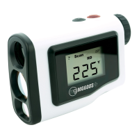
■ DISPLAY
COMPONENT FUNCTION
Main display Indicates present, MAX and MIN values, parameters, setting values and error
codes.
INDICATOR MODE FUNCTION INDICATOR MODE FUNCTION
Alarm Setting Indicates parameters in Alarm
Setting Mode.
(Refer to 8. SETTING ALARM
OUTPUT.)
Function Setting Indicates parameters in each
mode.
‘Zro’, ‘Spn’, ‘D/P’, ‘Tch’, ‘Fnc’, ‘Min’
and ‘Max’ indicators turn on in
combination depending on the
parameters.
Conrming
alarm
setpoints
‘HH’, ‘H’, ‘L’ or ‘LL’ indicator blinks
in conrming each alarm setpoint.
(Refer to 13.1 CONFIRMING
ALARM SETPOINTS.)
‘Max’ and ‘Min’ indicators blink
when a parameter is within invalid
range while setting.
Measuring Indicates the comparison result
between alarm setting values and
present values.
‘HH’ indicator turns on when the
HH alarm is tripped.
‘H’ indicator turns on when the H
alarm is tripped.
‘L’ indicator turns on when the L
alarm is tripped.
‘LL’ indicator turns on when the
LL alarm is tripped.
‘P’ indicator turns on when none
of the other alarms is tripped.
Measuring Indicates MAX or MIN value.
‘Max’ or ‘Min’ indicator turns on.
(Refer to 13.2 RETAINING MAX
AND MIN VALUES.)

 Loading...