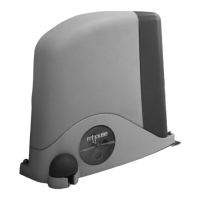
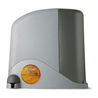
12 Instructions SL1
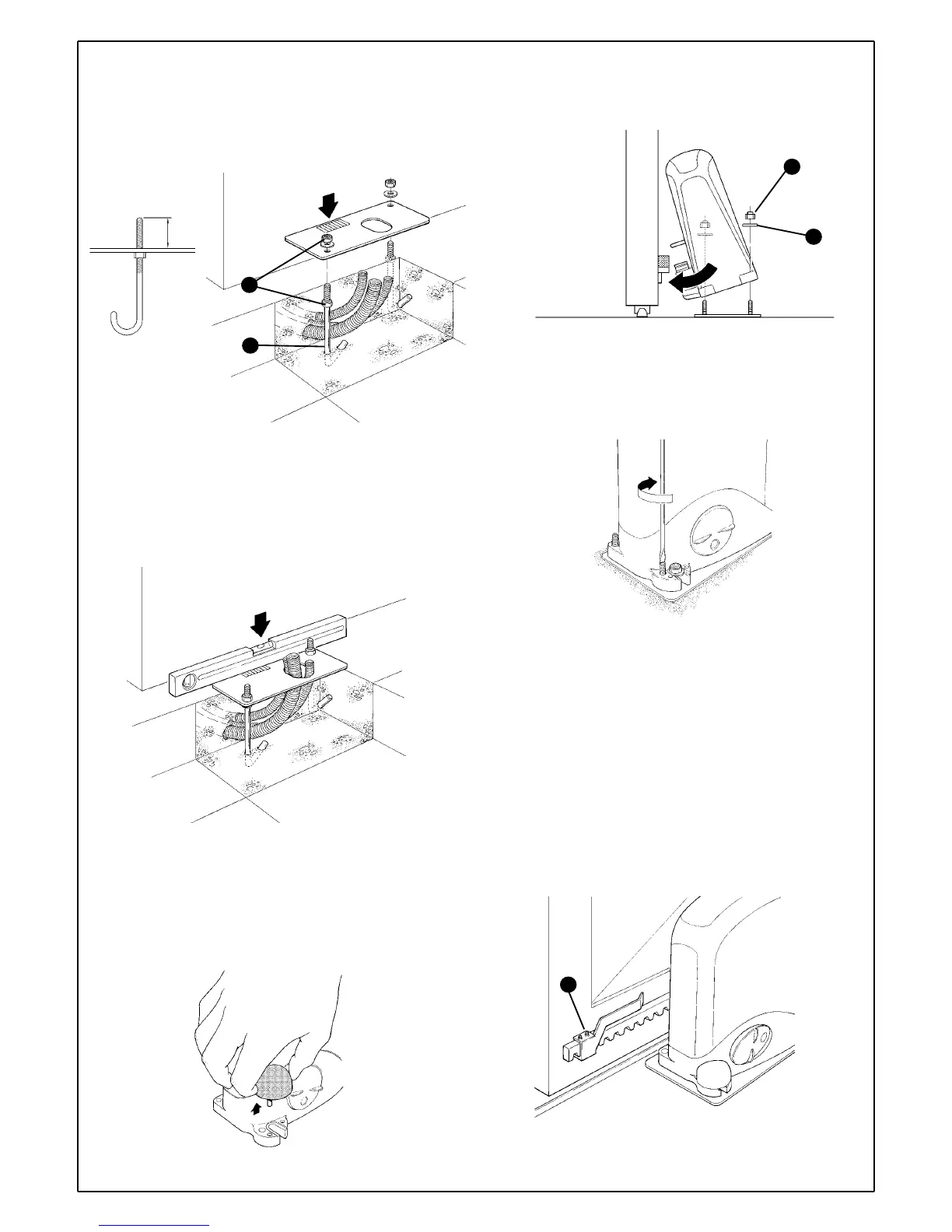
3 Fit the two bent pins [B] into the foundation plate and fix them above
and below with two M8 nuts [A]; make sure the projecting part does not
exceed the maximum height indicated in figure 27.
4Position the foundation plate making sure that the grooved side
(indicating the position of the pinion) faces the gate observing the
distances shown in figure 11.
5 Fit the conduits through the hole in the foundation plate.
6Pour the concrete.
7Make sure the plate is sunk into the concrete and that it is perfectly
level.
8 When the concrete is dry enough (after a few days), unscrew the two
nuts over the plate which will no longer be used.
9 Cut the cable conduits approximately 3-4cm above the plate.
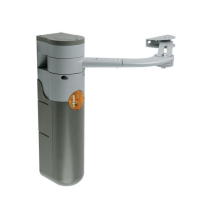
10 Remove the nut cover on the gearmotor.
11 Fit the gearmotor to the foundation plate underneath the rack. This
operation can be simplified by tilting the gearmotor so that the pinion can
easily pass under the rack. Tighten the two self-locking nuts [C] a little
after fitting the washers [D].
12 If necessary, adjust the height of the gearmotor (Max. 10mm) with the
4 dowels so that there is at least 1mm of play between the rack and the
pinion so that the gate does not weigh on the gearmotor. It is better to
fix the gearmotor without dowels as it will lie more firmly and securely on
the plate.
13 Make sure the gearmotor lies perfectly parallel with the gate. Then fix
it to the foundation plate and fully tighten the two self-locking nuts [C].
14 Release the gearmotor using the appropriate release keys (see the
"Gearmotor release" paragraph on page 36).
15 Open and close the gate several times by hand and make sure that
the rack is aligned with the pinion with a maximum tolerance of 5mm.
16 Fix the two limit switch brackets with the relative dowels [E] to the
outer sides of the rack.
Consider that the gate will slide for about another 30mm after the limit
switch cuts in. Position the brackets so that the gate does not jam.
17 To electrically connect the various devices, see paragraph 3.3.6
"Electrical Connections" on page 15.
Figure 27
36
B
A
Figure 28
Figure 30
C
D
Figure 31
Figure 32
E
Figure 29
 Loading...