8 Instructions SL1
3.1.1 Operating Limits
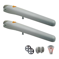
3.1.2 Tools and Materials
Make sure you have all the tools and materials needed to install
the system; make sure that they are in good condition and
serviceable according to current safety standards. See examples
in figure 16.
Figure 16
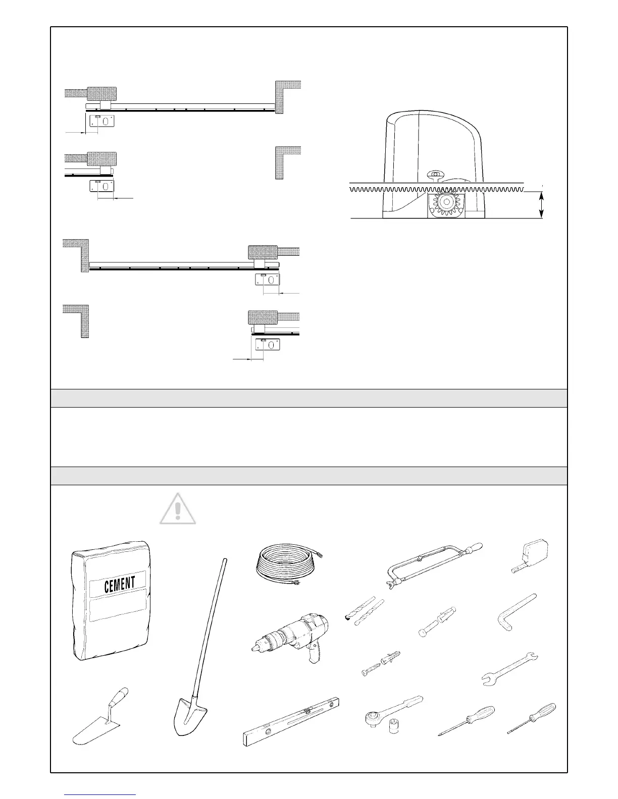
• To mount the limit switch brackets, the rack (and therefore the
gate) must project from the axis of the pinion by the distances
indicated in figure 13 (LT opening) and figure 14 (RT opening).
If the rack is already mounted on the gate, make sure its position
is compatible with the size limits indicated in figure 15 and check
that the pitch of the rack is module 4 (approx. 12mm).
Figure 15
Figure 13
200
170
170
200
Figure 14
77
Chapter 6 "Technical Characteristics" provides the fundamental data
needed to determine whether all the SL1 components are suitable for
the intended application.
In general, SL1 is suitable for the automation of gates up to 5 m long,
weighing up to 350 kg for residential applications.
The shape of the gate and the climatic conditions (e.g. presence of
strong wind) may reduce this maximum limit. In this case it is necessary
to measure the torque needed to move the leaves under the worst
conditions, and to compare it to the data provided in the technical
characteristics chart for the gearmotor.