Instructions SL1 23
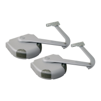
Normally the recognition of the devices connected to the ECSBus and
the STOP input takes place during the installation stage. However, if new
devices are added or old ones removed, the recognition process can be
gone through again by proceeding as follows:
1On the control unit, press the P2 [B] button and hold it down for at least
five seconds, then release it.
2Wait a few seconds for the control unit to finish recognizing the
devices.
3When the recognition stage is completed the P2 LED [A] should go off.
If the P2 LED flashes it means that an error has occurred: see paragraph
5.5 "Troubleshooting".
4 After you have added or removed any devices, the automation system
must be tested again according to the directions contained in paragraph
3.7.1 "Testing".
5.3.3 Recognition of Other Devices
B
A
Figure 67
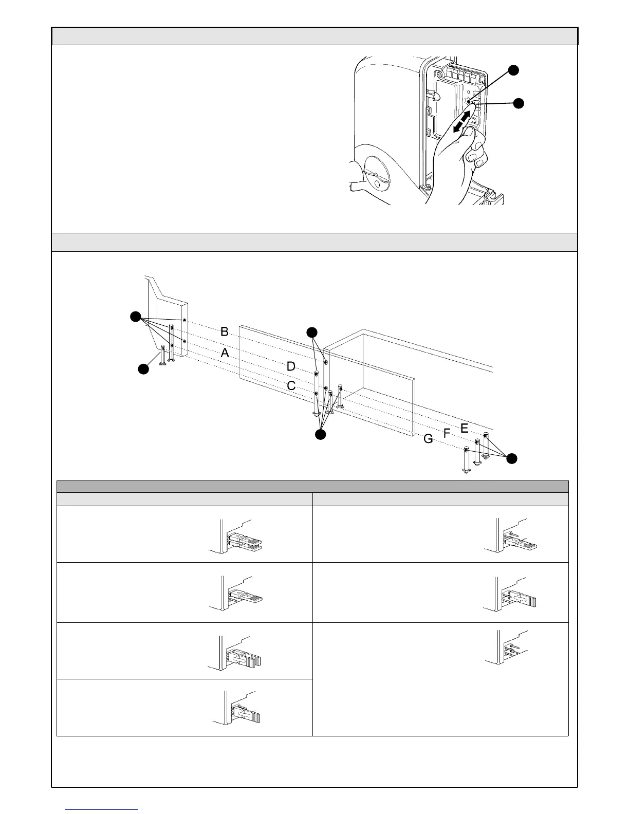
5.3.4 Addition of Optional Photocells
Table 9
Additional photocells can be installed at any time on top of those supplied with SL1. In an automation system for sliding gates these can be arranged
as shown in figure 68.
To ensure the correct recognition of the photocells by the control unit, the
former must be assigned addresses by means of jumpers. The address
allocation procedure must be performed on TX as well as RX (arranging the
jumpers in the same manner), but you must make sure that there are no other
pairs of photocells having the same address.
The photocells need to be assigned addresses to make sure that they are
correctly recognized among the other ECSBus devices, and in order to
assign the performed function.
External photocell h=50cm;
activated when gate closes
External photocell activated
when gate opens
Internal photocell activated
when gate opens
External photocell h=100cm;
activated when gate closes
Internal photocell h=100cm;
activated when gate closes
Single photocell for the entire
automation system activated
when the gate both opens
and closes
Photocell
Jumpers
A
B
C
G
D
Internal photocell h=50cm;
activated when gate closes
F
E
Photocell
Jumpers
Note: the two photocell elements (TX-RX) can be positioned
wherever you like.
Only if photocell G is used together with photocell B must the
position of the elements shown in figure 68 be respected.
Figure 68
Tx
Tx
Rx
Rx
Tx
 Loading...