22 Instructions SL1
With a radio transmitter memorized in mode 1,the adjustment values for
each parameter can be checked at any time using the following
sequence:
1Press buttons T1 and T2 on the radio transmitter simultaneously for at
least 5s.
2 Release the two buttons.
3Within 3 seconds, perform the action described in Table 7 based on
the parameter to be checked.
4Release the button when the flashing light starts flashing
5 Count the flashes and, based on their number, check the
corresponding value in table 6.
Example: If the flashing light flashes three times after you have pressed
T1 and T2 for 5s and then button T1, the pause time is set at 40s.
5.1.2 Checking the Adjustments with the Radio Transmitter
Table 7
Parameter Action
Pause time Press button T1 and hold it down
Pedestrian gate Press button T2 and hold it down
Motor force Press button T3 and hold it down
"OPEN" function Press button T4 and hold it down
5.2 Optional Accessories
In addition to the devices featured in SL1, other ones are available as
optional accessories designed to enhance the automation system.
PR1: 24V buffer battery for supply in the event of power failure. It
guarantees at least 10 complete cycles. When the system is powered by
the battery, the manoeuvre takes place only in "slow" speed mode.
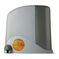
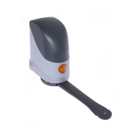
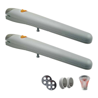
PT50: Pair of 500 mm posts with one photocell.
PT100: Pair of 1000 mm posts with two photocells.
For information on the new accessories, refer to the MHOUSE catalogue
or visit the site www.mhouse.biz.
5.3 Adding or Removing Devices
Devices can be added to or removed from the SL1 automation system
at any time.
Do not add any devices until you have made sure that they are
perfectly compatible with SL1; for further information contact
MHOUSE Customer Service.
5.3.1 ECSBus
ECSBus is a system that allows you to connect the ECSBus devices
using only two wires which carry both the power supply and the
communication signals. All the devices are connected in parallel on the
2 wires of the ECSBus itself; each device is individually recognized
because a univocal address is assigned to it during the installation.
The photocells, as well as other devices that adopt this system, can be
connected to ECSBus, such as safety devices, control buttons,
signalling lights etc. For information on the ECSBus devices, refer to the
MHOUSE catalogue or visit the site www.mhouse.biz.
The control unit recognizes all the connected devices individually through
a suitable recognition process, and can detect all the possible
abnormalities with absolute precision. For this reason, each time a
device connected to ECSBus is added or removed the control unit must
go through the recognition process; see paragraph 5.3.3 "Recognition of
Other Devices".
5.3.2 STOP Input
STOP is the input that causes the immediate interruption of the
manoeuvre (with a short reverse run). Devices with output featuring
normally open "NO" contacts (like the KS1 selector switch) and devices
with normally closed "NC" contacts, as well as devices with 8.2KΩ
constant resistance output, like sensitive edges, can be connected to
this input. Multiple devices, even of different type, can be connected to
the STOP input if suitable arrangements are made.
To do this, proceed as described in the following table:
Note 1. The NO and NC combination can be obtained by placing the
two contacts in parallel, and placing in series to the NC contact an
8.2K
Ω resistance (therefore, the combination of 3 devices is also
possible: NO, NC and 8.2KΩ ).
Note 2. Any number of NO devices can be connected to each other in
parallel.
Nota 3. Any number of NC devices can be connected to each other in
series.
Nota 4. Only two devices with 8.2KΩ constant resistance output can be
connected in parallel; if needed, multiple devices must be connected "in
cascade" with a single 8.2KΩ termination resistance.
Warning: if the STOP input is used to connect devices with safety
functions, only the devices with 8.2KΩ constant resistance
output guarantee the fail-safe category 3.
During the recognition stage the control unit, like ECSBus, recognizes
the type of device connected to the STOP input; subsequently it
commands a STOP whenever a change occurs in the recognized status.
Table 8
1st device type:
NO NC 8,2kΩ
2nd device type
NO
In parallel
(note 2)
(note 1) In parallel
NC
(note 1)
In series
(note 3)
In series
8,2kΩ
in parallel In series
in parallel
(note 4)