Instructions SL1 17
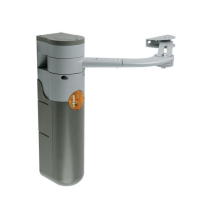
3.4 Power Supply Connection
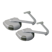
3.5 Initial checks
The connection of the SL1 control unit to the mains must be
made by a qualified electrician.
To carry out tests, insert the plug for SL1K in a power outlet; if necessary,
use an extension cord.
Figure 57
As soon as the control unit is energized, you should check the following:
1Make sure that the "ECSBus" LED [A] flashes regularly, with about one
flash per second.
2Make sure that the SAFE LED [B] on the photocells flashes (both on
TX and RX); the type of flashing is not important as it depends on other
factors; what is important is that the LED should not be steadily on or
steadily off.
3Make sure that the night light [C] on the KS1 key-operated selector
switch is on.
4 If the above conditions are not satisfied, you should immediately switch
off the power supply to the control unit and check the cable connections
more carefully. For more useful information see also chapters 5.5
"Troubleshooting" and 5.6 "Diagnostics and Signals".
Figure 58
Figure 60
Figure 59
A
B
C
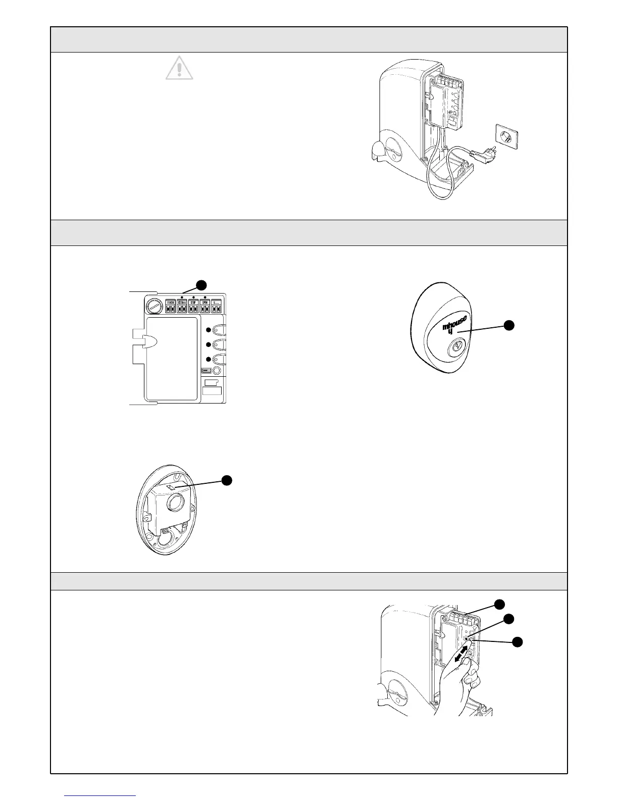
3.5.1 Recognition of Connected Devices
When you have completed the initial checks, the control unit must
recognize the devices connected to it on the "ECSBus" and "STOP"
terminals.
1On the control unit, press the P2 button [C] and hold it down for at
least three seconds, then release the button.
2Wait a few seconds for the control unit to finish recognizing the
devices.
3When the recognition procedure is completed, the STOP LED [A] must
remain on, while the P2 LED [B] must go off. If the P2 LED flashes it
means that an error has occurred: see paragraph 5.5 "Troubleshooting".
The connected devices recognition stage can be repeated again at any
time, even after the installation (for example, if an additional photocell is
installed); just repeat the procedure starting from step 1.
Figure 61
B
A
C
 Loading...