3.3.4 KS1 Key-Operated Selector Switch
Instructions SL1 13
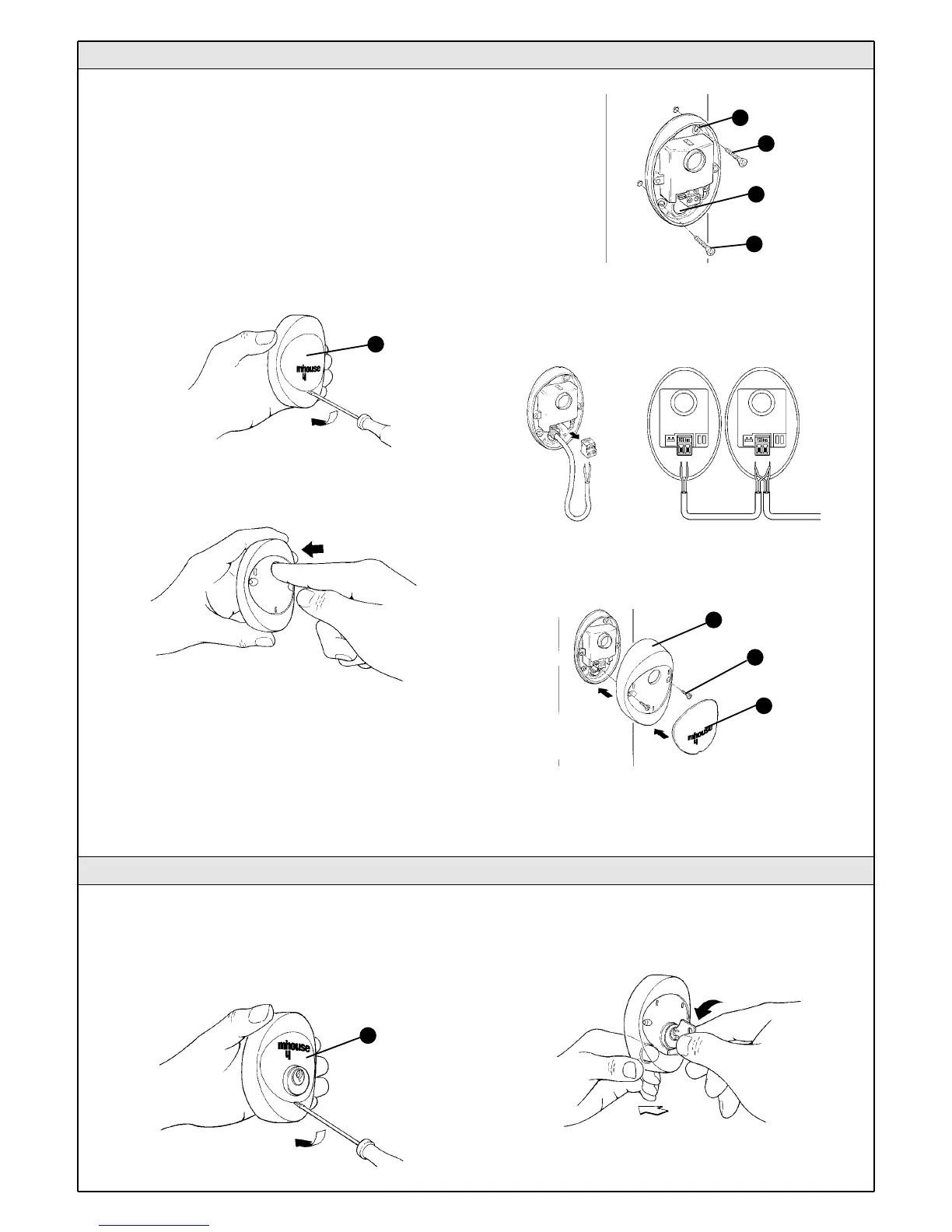
3.3.3 Photocells
1Select the position of the two elements that make up the photocell (TX
and RX) observing the following directions:
• Position them at a height of 40-60 cm from the ground, on both sides
of the area to be protected, on the street side of the installation and as
close as possible to the edge of the gate, no farther than 15 cm.
• Point transmitter TX towards receiver RX, with a maximum tolerance of 5°.
• In the selected locations there must be a conduit for threading the
cables.
2 Remove the front glass [A] by prising it out with a slotted tip
screwdriver applied to the bottom.
3Press the lens in order to separate the two shells.
4Breach two of the four holes [B] at the bottom with a screwdriver.
5Position the photocell at the point where the conduit arrives; the hole
at the bottom [D] should match the point where the cables come out of
the wall; mark the drilling points using the bottom as reference.
6Drill the holes in the wall using a hammer drill with a 5 mm bit and insert
the 5 mm screw anchors.
7 Secure the bottom with the screws [C].
8 Connect the electric cable to the appropriate TX and RX terminals.
From an electrical viewpoint, TX and RX must be connected in parallel as
shown in figure 36. It is not necessary to observe any polarity. The
terminals can be removed in order to facilitate the operations; make the
connections and then reinsert them.
9 Secure the cover shell [E] using the two screws [F] and a Phillips
screwdriver. Then insert the glass [G], pressing it gently to close it.
Figure 34
Figure 35
Figure 36
Figure 37
B
C
D
C
E
F
G
Figure 33
A
TX
RX
1 Determine the position of the selector switch; it must be installed
outdoors, alongside the gate and at a height of approx. 80 cm, so that
it can be used by people of different height.
2 Remove the front glass [A] by prising it out with a slotted tip
screwdriver applied to the bottom.
3To separate the bottom from the shell you need to insert the key and
keep it turned, then pull with a finger inserted in the hole for the passage
of the cables.
Figure 38
A
Figure 39
 Loading...