16 Instructions SL1
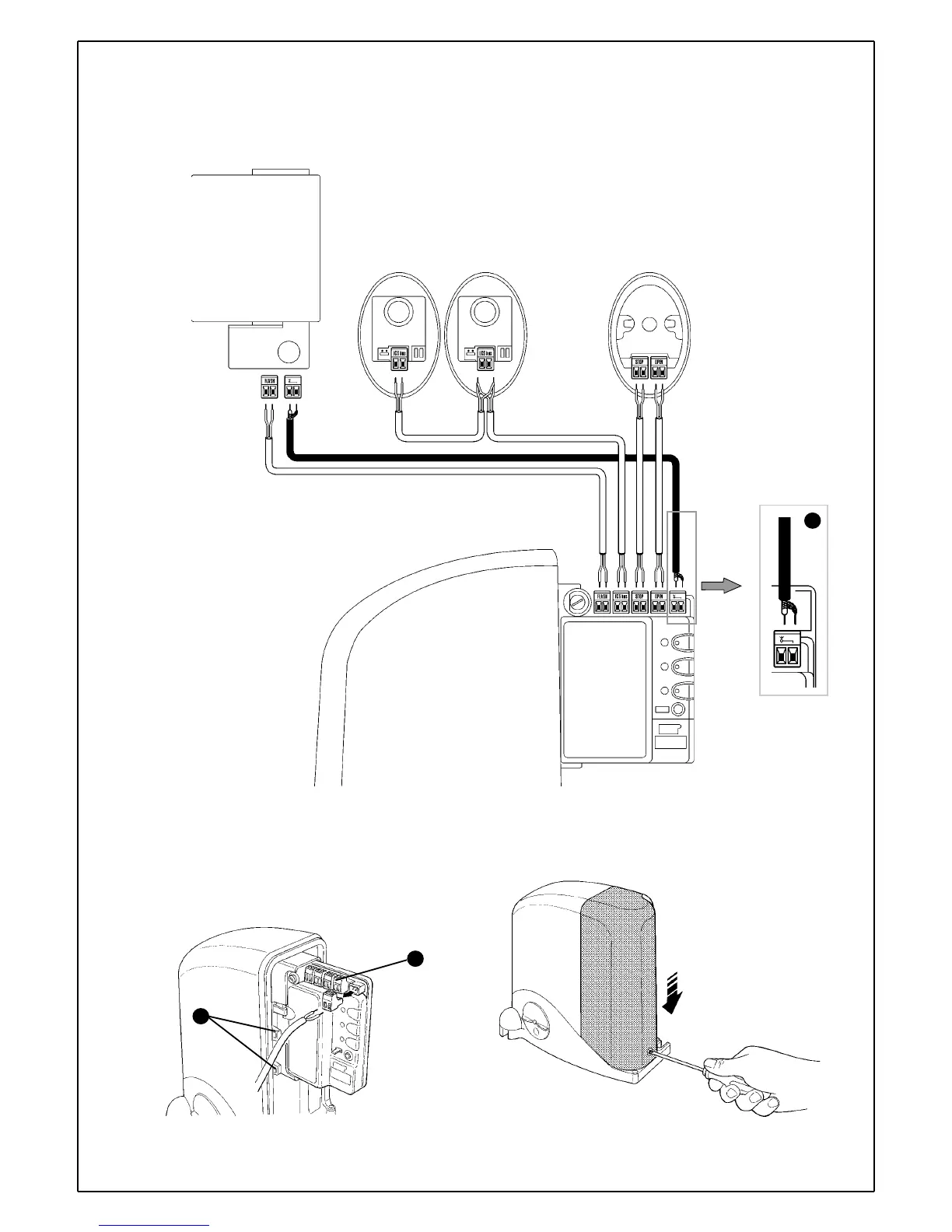
5 Refer to figure 54 for the electrical extra low voltage connection of the
various devices to the control unit terminals.
• The terminals have the same colour coding as the corresponding
devices; for example, the grey terminal (OPEN) of the KS1 selector must
be connected to the grey terminal (OPEN) of the control unit.
• For most connections you do not need to observe any polarity; only
for the shielded cable of the aerial it is necessary to connect the central
core and the shield as shown in detail [A].
The terminals can be removed in order to facilitate the operations [A] as
shown in figure 55; make the connections and then reinsert them.
When you have completed the connections, use clamps to secure the
cables to the appropriate fasteners [B].
6Close the side cover of the SL1K gear motor by sliding it on from
above and tighten the screw with a screwdriver.
FL1
PH1
PH1
KS1
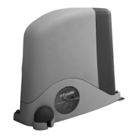
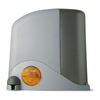
SL1K
Figure 54
B
A
Figure 55
Figure 56
B
TX
RX
 Loading...