© Microhard Systems Inc. 25
3.0 Hardware Features
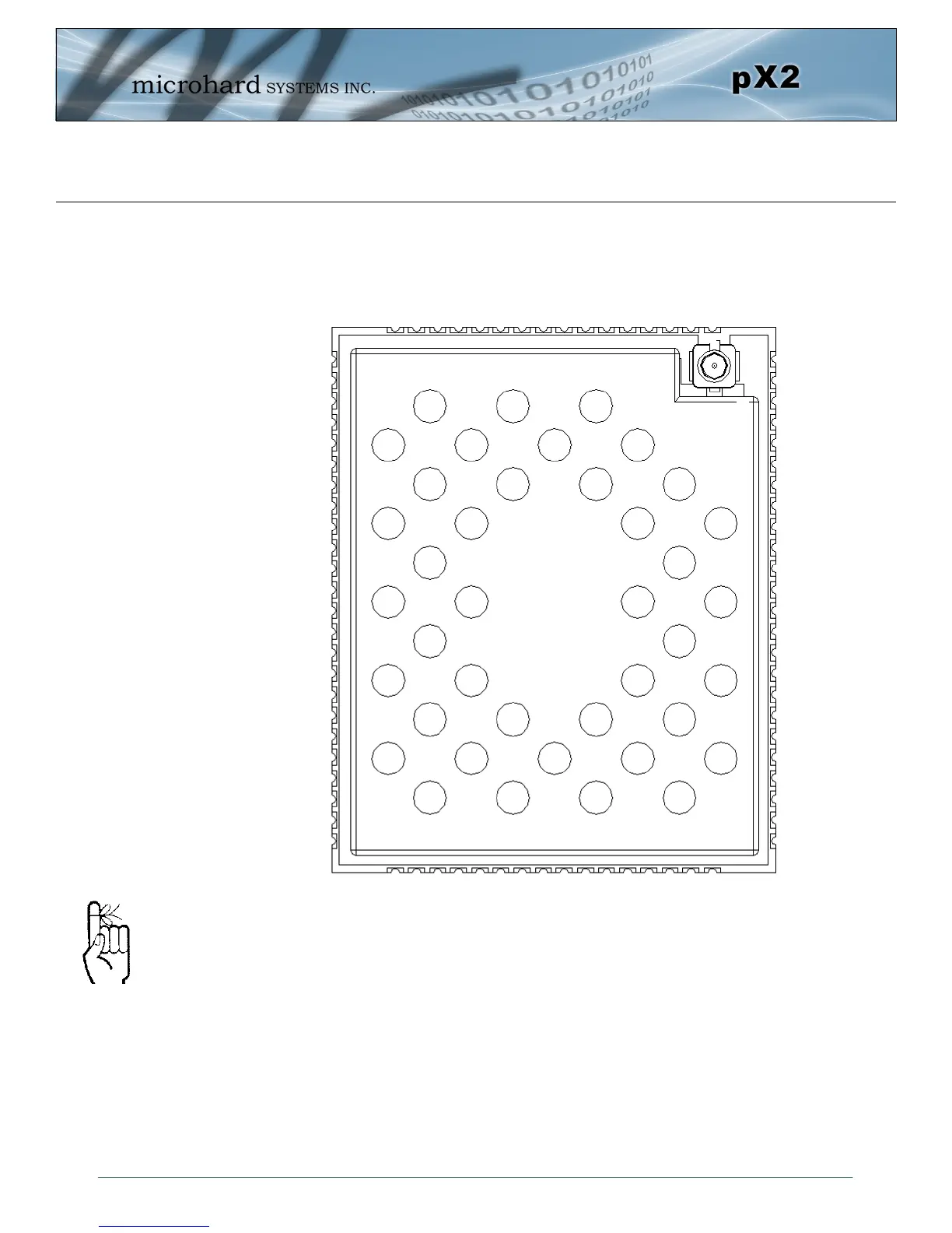
Drawing 3-4: pX2 80-pin OEM Connection Info
3.1.5 Pico OEM Pin Descriptions
The above drawing depicts a top view of the pX2 OEM Module. The corner pads (1, 25, 41,
and 65) are printed directly on the bottom of the PCB for easy identification.
A full description of the connections and function of each pin is provided on the pages that
follow.
Inputs and outputs are
3.3V nominal (3.0V min
— 3.6V max) unless
otherwise specified.
GND
VRF
VRF
Vcc
Vcc
ETH0 LINK_LED (LAN)
NC
RX_P0 (LAN)
RX_N0 (LAN)
TX_N0 (LAN)
TX_P0 (LAN)
NC
NC
NC
pX2
(Top View)
NC
NC
1
GND
DNC
DNC
DNC
DNC
DNC
NC
NC
NC
NC
CPU STATUS LED
NC
ETH_BIAS
USB_MODE
CONFIG
RESET
GND
USBA_DP
USBA_DM
RSSI LED1
RSSI LED2
RSSI LED3
ETH4 LINK_LED (WAN)
2
3
4
5
6
7
8
9
10
11
12
13
14
15
16
17
18
19
20
21
22
23
24
40 39 38 37 36 35 34 33 32 31 30 29 28 27 26 25
41
42
43
44
45
46
47
48
49
50
51
52
53
54
55
56
57
58
59
60
61
62
63
64
80 79 78 77 76 75 74 73 72 71 70 69 68
67 66 65
LED RX
LED TX
GND
GND
GND
GND
GND
GND
GND
GND
GND
GND
GND
GND
GND
GND
GND
NC
NC
NC
NC
TX_P4 (WAN)
TX_N4 (WAN)
RX_P4 (WAN)
RX_N4 (WAN)
GND
GND
NC
Serial RxD
Serial TxD
Serial DSR
Serial CTS
Serial DTR
NC
Serial RTS
NC
NC
NC
NC
GND
GND