Classic Manual Rev L
22 | P a g e 1 0 - 0 0 1 - 1 R E V L
Connecting the Classic to Two MNGPs/Network Cable
The Classic can be controlled with two MNGPs at the
same time. This will help when the Classic is in a shop and
there is a considerable distance between the Classic and
the controlling point (office, inside house, garage etc.).
Instead of going to the Classic to check status or to change
a setting, the user can run a cable to the controlling point
and see the Classic in a second MNGP. The cable is a 6-
wire phone cable. Connect one side of the extension cable
to the jack in the Classic labeled SLAVE/OUT and the
other end to the second MNGP. Since the Classic transmits
power and data signals through the phone cable to the
MNGP, the length of the cable is limited to 100 feet.
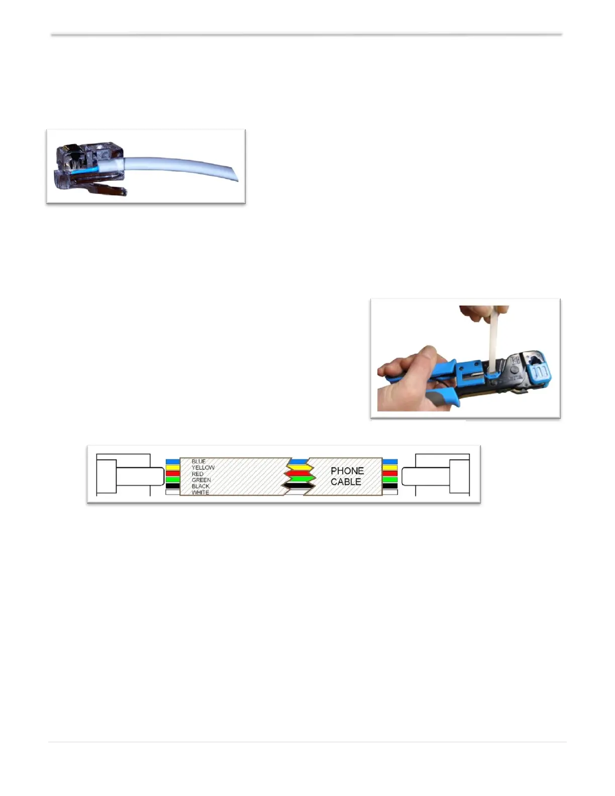
MidNite only offers a 3-ft cable as an optional accessory. If
you are making your own cable, insert cable end all the
way into the phone terminal to get a good contact. Use
phone crimping pliers to crimp both ends of the cable. We
recommend using flat phone cable for extension, just
because it is easier to work with. Reference Figures 13 and
14. Ensure the color and position of the wires are as
shown in Diagram 4. Use terminal connector tab as
reference.
Connecting the Classic to the Internet
The Classic supports standard 10/100-base T Ethernet networks. For Gigabit networks you will
need a common network switch that is capable of mixed mode operation. The Classic may also be
placed on a, b, g, or n wireless networks by using a wireless network bridge device. Depending on
your network you may use one of the topographies detailed in Example 1 through 4 below. Note
that the switch may be self-contained or, in many cases, may already be integrated into your cable or
DSL modem. Refer to Figure 12 for Ethernet connector location in the Classic.