Classic Manual Rev L
46 | P a g e 1 0 - 0 0 1 - 1 R E V L
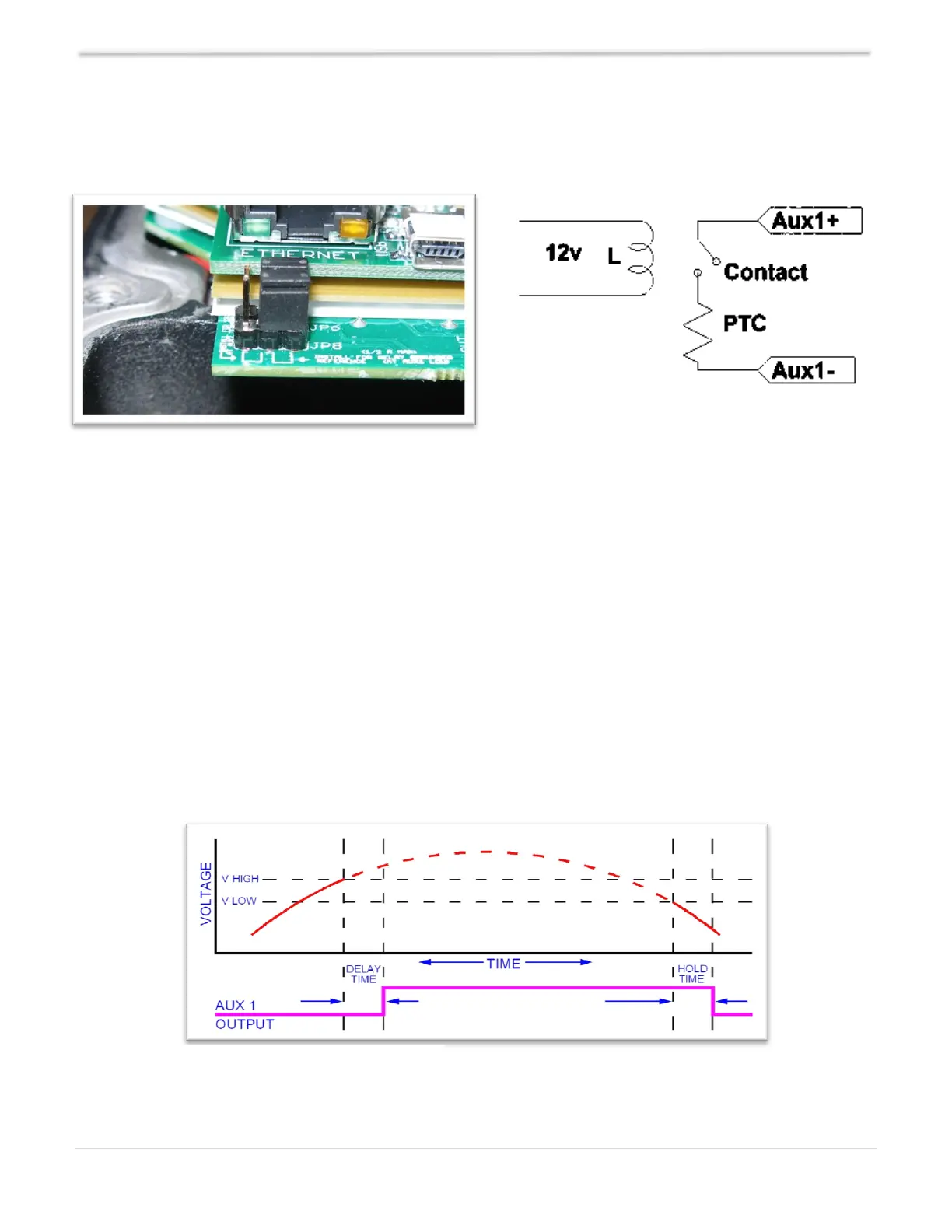
When AUX 1 is used to supply 12V out, JP6 and JP8 must be in the position shown in Figure 20. The
basic schematic of how this works is shown above in Diagram 6. The 12V out is more like 14.5V.
The maximum current through AUX 1 should not exceed 200mA.
AUX 1 - Dry Contact
To configure AUX 1 to use the internal relay, JP6 and JP8 must be in the position shown in Figure 21.
This configuration is commonly known as “dry contact” because it does not provide 12V at the AUX
1 terminals; it acts more like an isolated switch (to the ratings of the relay).
AUX 1 Volts/Time Graph
Diagram 8 is the AUX 1 Function Graph showing the relationship between voltage and time. The axis
labeled VOLTAGE could be battery, PV, wind input voltage, etc., depending on the function selected
by the user. V HIGH is the upper voltage limit: when the voltage reaches this limit, the DELAY TIME
will start; when the DELAY TIME expires, AUX 1 will change state and stay there until the voltage
drops below the V LOW set point, then another timer called HOLD TIME will start and when this
expires the output will go back to the original state.
Diagram 8 – AUX 1 Function Graph