Technical Information
T300 Series Clothes Dryer (Condenser)
T300 Series Clothes Dryer (Condenser) – List of Figures
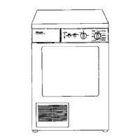
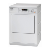
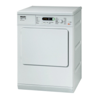
Figure 1-1: Overview of Model Numbers (Continued on Figure 1-2) .............................. 8
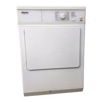
Figure 1-2: Overview of Model Numbers (Continued from Figure 1-1)........................... 9
Figure 2-1: Draining Condensate to the Rear ............................................................... 17
Figure 2-2: Opening the Condenser Drawer................................................................. 18
Figure 4-1: Electronic Residual Moisture Detection Unit EF 102.................................. 19
Figure 4-2: Electronic Residual Moisture Detection Unit EF 202.................................. 20
Figure 5-1: Opening the Front Panel ............................................................................ 21
Figure 5-2: Electrical Components (T 368 C, T 369 C)................................................. 23
Figure 5-3: Electrical Components (T 368 C from Machine no. Prefix 11/) .................. 24
Figure 5-4: Electrical Components (T 369 C-2) ............................................................25
Figure 5-5: Electrical Components (T 377 C, T 378 C)................................................. 26
Figure 5-6: Heater Bank Removal 1 ............................................................................. 27
Figure 5-7: Heater Bank Removal 2 ............................................................................. 28
Figure 5-8: Heater Bank Removal (from Machine Nos. Prefix 10/ or 11/) ....................29
Figure 5-9: Fan Unit Removal 1.................................................................................... 30
Figure 5-10: Fan Unit Removal 2.................................................................................... 31
Figure 5-11: Fan Unit with Drum Drive Motor Removal .................................................. 32
Figure 5-12: Removing the Drive Belt............................................................................. 33
Figure 5-13: Removing the Pump ................................................................................... 33
Figure 5-14: Removing the Unit ...................................................................................... 34
Figure 5-15: Condensate Pump Replacement................................................................ 35
Figure 5-16: Drum Drive Motor Removal ........................................................................ 36
Figure 5-17: Cooling Fan Removal 1 (Machine Nos. without Prefix) .............................. 37
Figure 5-18: Cooling Fan Removal 2 (Machine Nos. without Prefix) .............................. 38
Figure 5-19: Cooling Fan Removal 3 (Machine Nos. without Prefix) .............................. 38
Figure 5-20: Cooling Fan Removal (Machine Nos. with Prefix 10/ or 11/)...................... 39
Figure 5-21: Drum Drive Belt Replacement 1 ................................................................. 40
Figure 5-22: Drum Drive Belt Replacement 2 ................................................................. 41
Figure 5-23: Drum Drive Belt Replacement 3 ................................................................. 41
Figure 5-24: Drum Removal............................................................................................42
Figure 5-25: Simple, Folded Drum Edge ........................................................................ 42
Figure 5-26: Rolled Drum Edge ......................................................................................43
Figure 5-27: Fill Ring Seal Replacement ........................................................................46
Figure 5-28: Door Seal Replacement ............................................................................. 47
Figure 6-1: Connecting the 7-Pole Plug........................................................................ 53
Figure 6-2: Connecting a Multimeter............................................................................. 53
Figure 6-3: Setting the Drying Program ........................................................................54
6