Temperature Control Units : MFC with G Series Instrument
Page: 16
Milacron Process Support Business
4165 Halfacre Road Batavia, Ohio 45103
Phone: 513-536-2584
www.milacron.com
1. The amount of cooling provided by the unit depends on:
a. The cooling valve size
b. The pressure differential across the valve
c. The temperature difference between the unit set point and the cooling
water temperature
d. The cooling valve position
2. Consult factory when selecting the correct cooling valve for your application.
3. In general the standard ½” AVT modulating cooling valve will provide
approximately 24,0000 Btu/hr (7 kW) of cooling per every 10°F difference
between the cooling water temperature and the process set point based on
25 psi delta p across the cooling valve with ½” supply & return connections.
Connecting the unit with ¾” or 1” cooling water supply and return connections will
increase the cooling capacity of the unit.
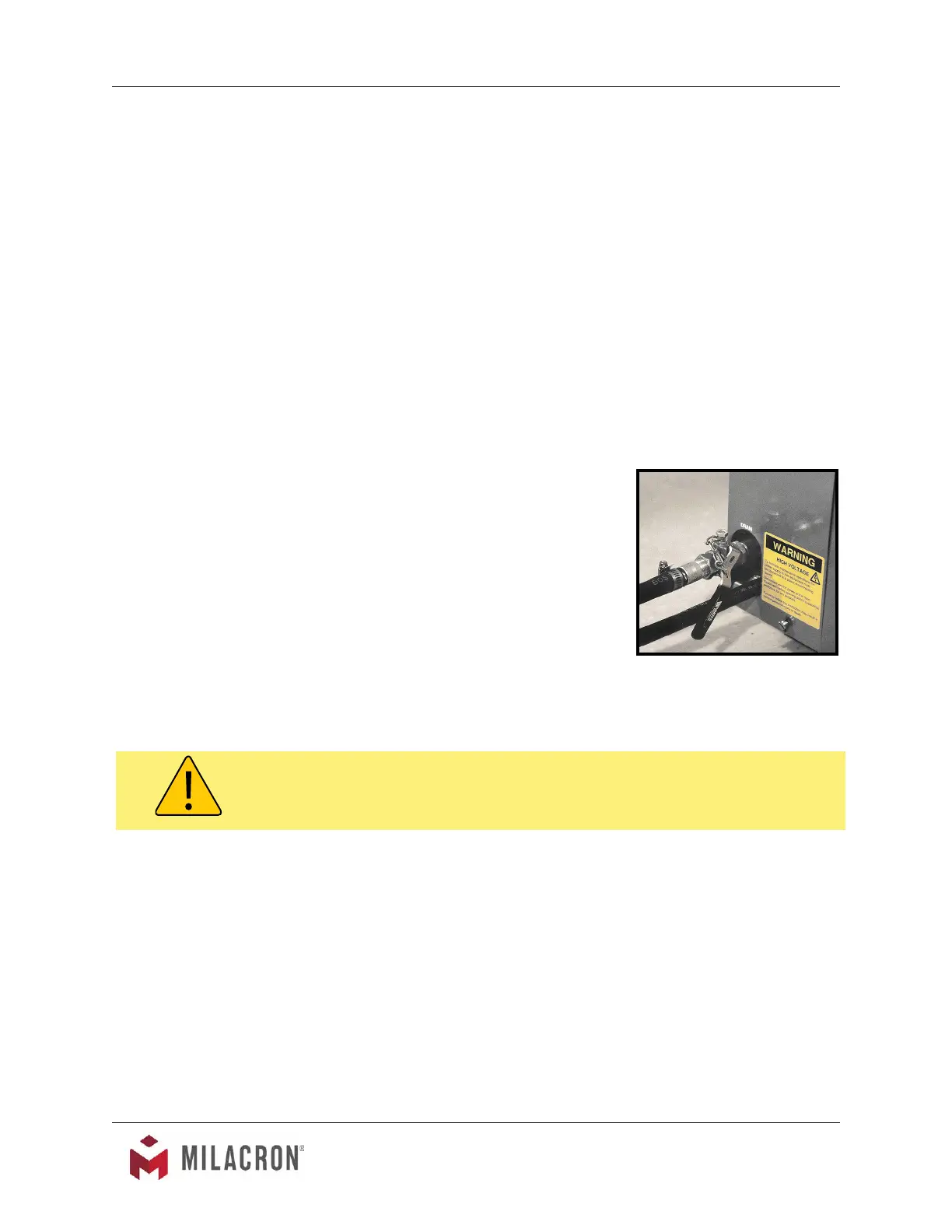
C. For most applications, the drain line should not be
valved. However, for installations with a pressurized
drain system, it may be necessary to install a valve in
the drain line. In such cases, the installed valve must
be fully opened after installation and the valve handle
removed to prevent operating the unit with a closed
drain valve. The valve handle can be reattached to the
valve body when it is necessary to close the valve.
D. CAUTION: The unit must never be operated with
a closed drain line valve. A closed drain line valve
prevents adequate system cooling and will lead to unit
overheating. Overheating of the unit may lead to unit
damage and/or serious personal injury.
2.5 ELECTRICAL CONNECTION
A. Standard Models
1. Electrical power supply requirements for standard units are identied on the
equipment data tag. Verify that available voltage supply is the same as the unit’s
voltage requirements.
WARNING: DO NOT CONNECT THE UNIT TO A VOLTAGE SUPPLY SOURCE
NOT EQUAL TO THE UNIT’S VOLTAGE REQUIREMENTS AS SPECIFIED ON
THE UNIT’S DATA PLATE.
Typical drain valve installation
(Shown on S-925 model).
WARNING: Never operation the Temperature Control Unit with a closed drain.