Temperature Control Units : MFC with G Series Instrument
Page: 45
Milacron Process Support Business
4165 Halfacre Road Batavia, Ohio 45103
Phone: 513-536-2584
www.milacron.com
2. Motor overload switch opened. The electric motor is protected from overload
conditions by a set of thermal overload relays. These relays will open (trip). If
the overload relay is open, it must be reset before operation can continue. An
excessive ow condition must be isolated and corrected immediately.
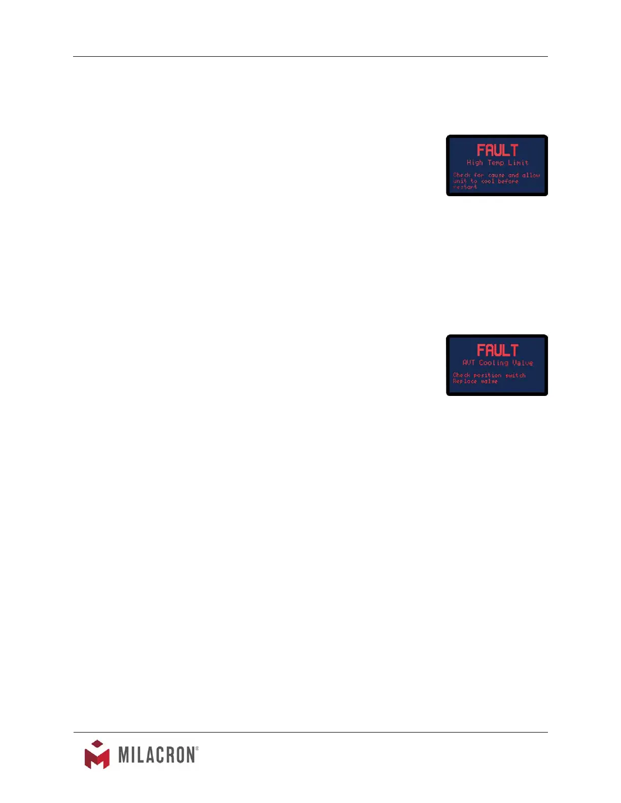
3. High temperature limit switch open. The unit is
prevented from operations at temperatures exceeding
256°F by a “high temperature limit switch”. This switch
is installed in the To Process temperature sensor. If this
switch is open (due to a high temperature condition), the
unit cannot be started and must “cool down” before the
“high temperature limit switch” will automatically reset.
4.4 UNIT OVERHEATS
A. This is evidenced by To Process temperatures consistently above the selected setpoint
temperature. Overheating is also evidenced by a To Process temperature that continues
to escalate above the setpoint temperature with no apparent cooling action, even though
the Cool light is on. Extreme overheating is evidenced by To Process temperatures over
256°F. The operator should check for the following conditions:
1. Inadequate water supply pressure. The unit must be
supplied with adequate water ow to provide cooling
when required. The minimum pressure differential
between the water supply and drain to achieve full
cooling capacity is 10 PSI. The minimum water supply
pressure is 20 PSI for setpoints from 180°F and under.
A chart in Section 2.3 lists water supply pressures for
setpoint above 180°F. A drop in water supply pressure
operation will cause the pump to stop and a safety fault to be displayed.
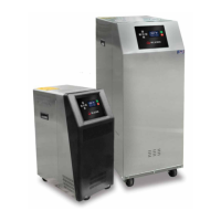
2. AVT
TM
valve defective. The instrument opens and closes the AVT
TM
cooling valve
in incremental steps between 0 to 100% as prescribed by the current process
load. A continual discharge stream of process water to drain is present under
most operating conditions (except at full heat-up). This allows the unit to maintain
virtual straight-line control of process water temperature. If the AVT
TM
valve
becomes clogged with process water debris or scaled with mineral deposits, its
operation is hindered or fully prevented and adequate process water discharge
to drain is prevented. The operator must remove the AVT
TM
valve and remove
any loose debris. Massive debris or scale deposits may necessitate replacement
of the AVT
TM
valve. The procedure for servicing the AVT
TM
valve is outlined in
Section 5.3 of this manual.
3. Drain line obstruction. The operator must determine if the drain line is
obstructed by the following conditions. Section 2.4 outlines the parameters of
correct drain line installation.
a. Closed drain line valve. An installed but partially or fully closed valve
in the drain line prevents full discharge to drain and contributes to an
overheating condition. The operator should determine the drain line is
open.
AVT Valve Fault Screen.
High Temp Limit Fault
Screen.