Temperature Control Units : MFC with G Series Instrument
Page: 51
Milacron Process Support Business
4165 Halfacre Road Batavia, Ohio 45103
Phone: 513-536-2584
www.milacron.com
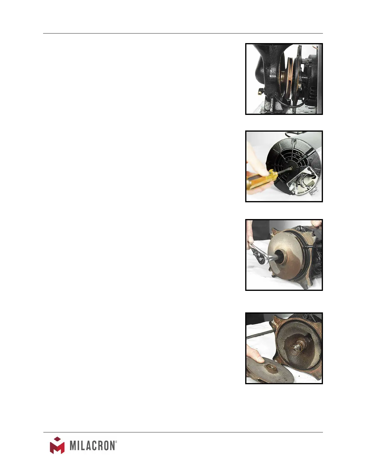
9. Locate and remove the dust cap from the
motor to expose slotted motor shaft. The
motor shaft is free to rotate, but must be
secured to remove the impeller. To secure
the motor shaft, insert a at bladed screw
driver in slot to hold the shaft stationary
(gure 5.1F).
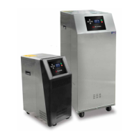
10. Locate and remove impeller locking screw
(gure 5.1G). Using a socket and ratchet,
the impeller retaining screw can be removed.
Once removed, the impeller can be
“unthreaded” from the motor shaft to expose
the pump seal assembly.
11. Remove all seal parts (gure 5.1H). Note
seal component arrangement to facilitate
reassembly.
12. Clean the motor shaft and lubricate with a
mild soap solution. Note: Oil must never be
used as a lubricant as it will damage the
rubber parts of the seal assembly.
13. Install new stationary seal member in pump
casing cavity (gure 5.1H). Be certain the
stationary seal member is fully squared and
seated in cavity.
14. Slide the rotating member onto the lubricated
pump shaft (gure 5.1I). Be certain not to
damage or tear the rubber bellows assembly.
15. Place the spring onto the rotating member.
16. Align the tension spring and rotating member
before reinstalling the impeller (gure 5.1J).
Be certain the spring and rotating member
are aligned before the impeller is fully
tightened and the impeller retaining screw is
reinstalled.
17. Clean the pump casing, cavities, impeller
and O-ring before reassembly.
18. Mate the motor and adapter to the pump
casing. Reinstall the 4 pump casing bolts.
19. Reconnect the motor power cord and leads.
Impeller
Figure 5.1E
Motor shaft
Figure 5.1F
Removing impeller
locking screw with ratchet
Figure 5.1G
Seal components
Figure 5.1H