Temperature Control Units : MFC with G Series Instrument
Page: 53
Milacron Process Support Business
4165 Halfacre Road Batavia, Ohio 45103
Phone: 513-536-2584
www.milacron.com
5.2 HEATER REPLACEMENT
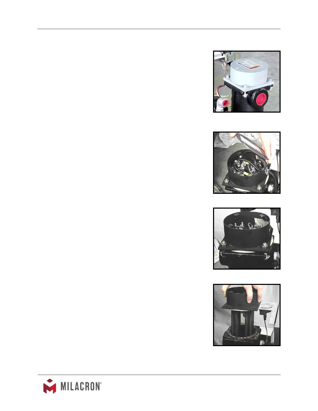
A. The heater is a ange mounted assembly and inserted
into the cast cylinder tank and secured by 4 bolts (gure
5.2A).
B. The operator can determine if the heater requires
replacement when the heater draws “0” amps or when a
continuity check of each heater element is negative.
C. Generally, heaters fail due to low water ow, low
water pressure, air in the system or defective heating
elements.
D. The operator should follow this procedure to replace the
heater:
1. Disengage operations and be certain all system
pressure is relieved and the unit’s pressure
gauges read “0”.
2. Disengage main power supply. Verify the Power
light on the display is “off”.
3. Remove the lift-off access panel and set aside
4. Drain machine. The machine can be drained by
removing the pump casing drain plug.
5. Remove heater’s junction box cover to locate
wiring connections. The operator should
note the wiring connections to ensure correct
reinstallation (gure 5.2B).
6. Disconnect the three power leads from the
heater terminals. Remove the power cord from
the junction box.
7. Remove the 4 heater mounting bolts (gure
5.2C).
8. Remove heater (gure 5.2D).
9. Before the new heater is installed, the mating
surface of the cast tank should be cleaned.
Once cleaned, place the new heater gasket
onto the tank mating surface. Coat the mating
surface with a high temperature gasket sealant.
10. Set new heater into tank. Aligning the bolt
pattern of the heater and tank anges.
Heater
Figure 5.2A
Heater mounting bolts
Figure 5.2C
Heater junction wires
Figure 5.2B
Remove heater
Figure 5.2D
 Loading...