Temperature Control Units : MFC with G Series Instrument
Page: 57
Milacron Process Support Business
4165 Halfacre Road Batavia, Ohio 45103
Phone: 513-536-2584
www.milacron.com
NOTE: Important... the valve stem should be in this position (as indicated in the
diagram) and the valve should be CLOSED. If the valve is open, manually turn
the square stem 90° so that the valve is closed.
E. To service the valve components, continue with steps 13 - 20:
12. Be certain the unit is totally depressurized with the unit’s pressure gauges
reading “0”. The unit should be drained if possible.
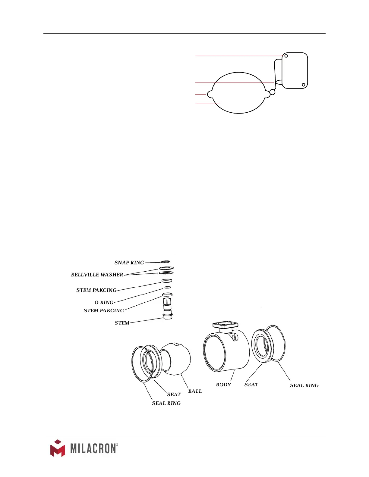
13. The valve assembly is a ball valve specially designed only to work with the AVT
TM
motor. The valve assembly is secured to the cooling cylinder by a top plate and
4 mounting screws. The drain connection originates at the valve top plate with
a brass elbow and close nipple tting. The connection can be maintained when
servicing the valve.
Coupling
Lobe
Switch
MTG Screws
 Loading...