Temperature Control Units : MFC with G Series Instrument
Page: 60
Milacron Process Support Business
4165 Halfacre Road Batavia, Ohio 45103
Phone: 513-536-2584
www.milacron.com
8. Replace the motor starter and overload block. Adjust the overload block settings
for the current draw at the new voltage (gure 5.4F).
9. Once a voltage change is complete, be certain the unit is properly connected to
the new voltage supply, as outlined in section 2.5 of this manual. Restart unit
operations according to section 3 of this manual.
4
7
208/240
4
5
6
1
L1
7
2
L2
8
3
L3
9
460/480
1
L1
2
L2
3
L3
5
8
6
9
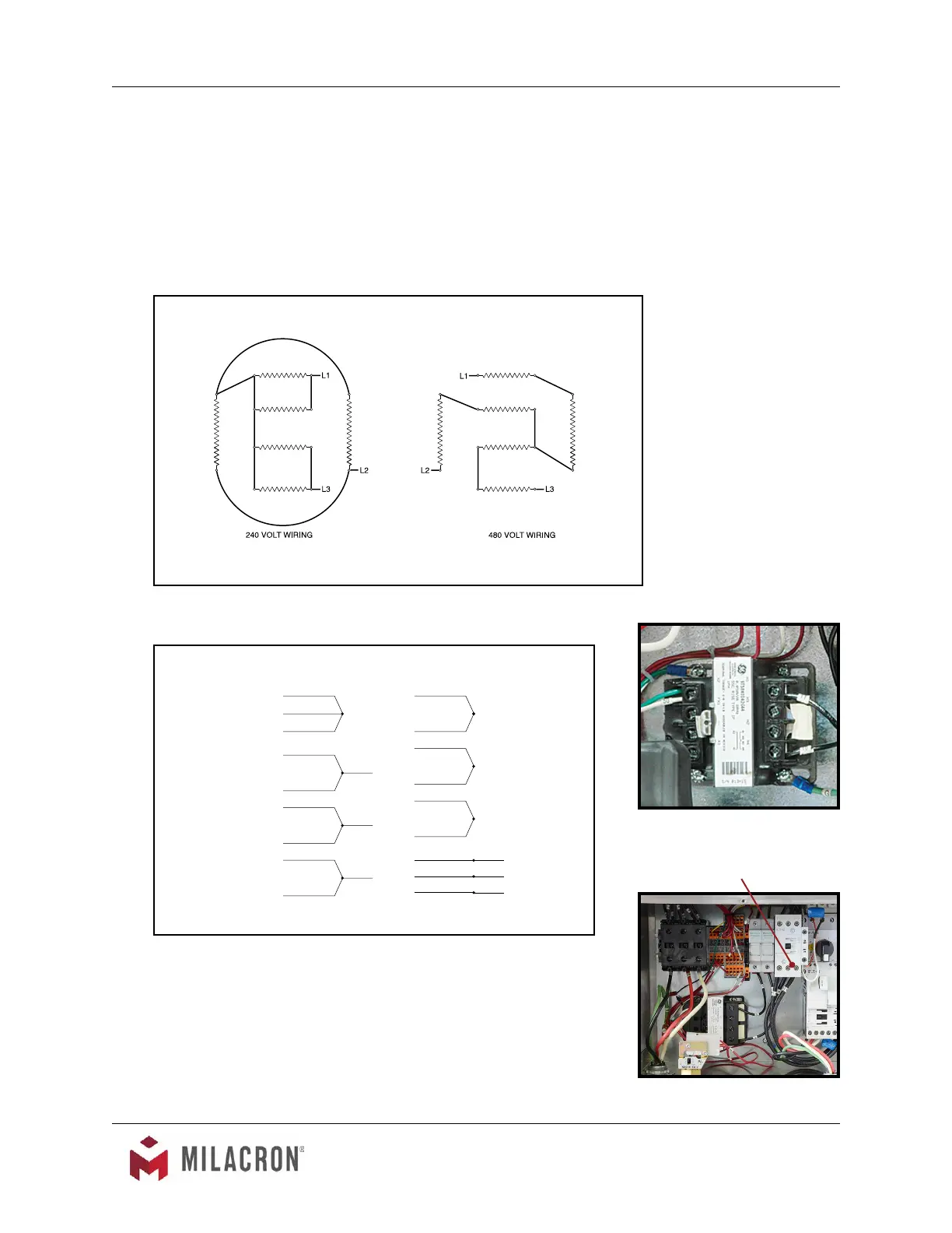
Figure 5.5D
Wiring schematics for 240 and 480 volt pump
motors
Transformer
Figure 5.5E
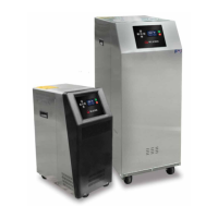
Figure 5.5C
Wiring schematics for 240 and 480 volt heaters Revised 4/11
Motor Starter and Overload
Block
Figure 5.5F