OM-273473 Page 31
Existing
Input Power
Supply
Ground
Robot
Control
Welding
Power
Source
Input Power
Supply Line
Line
Disconnect
Switch Box
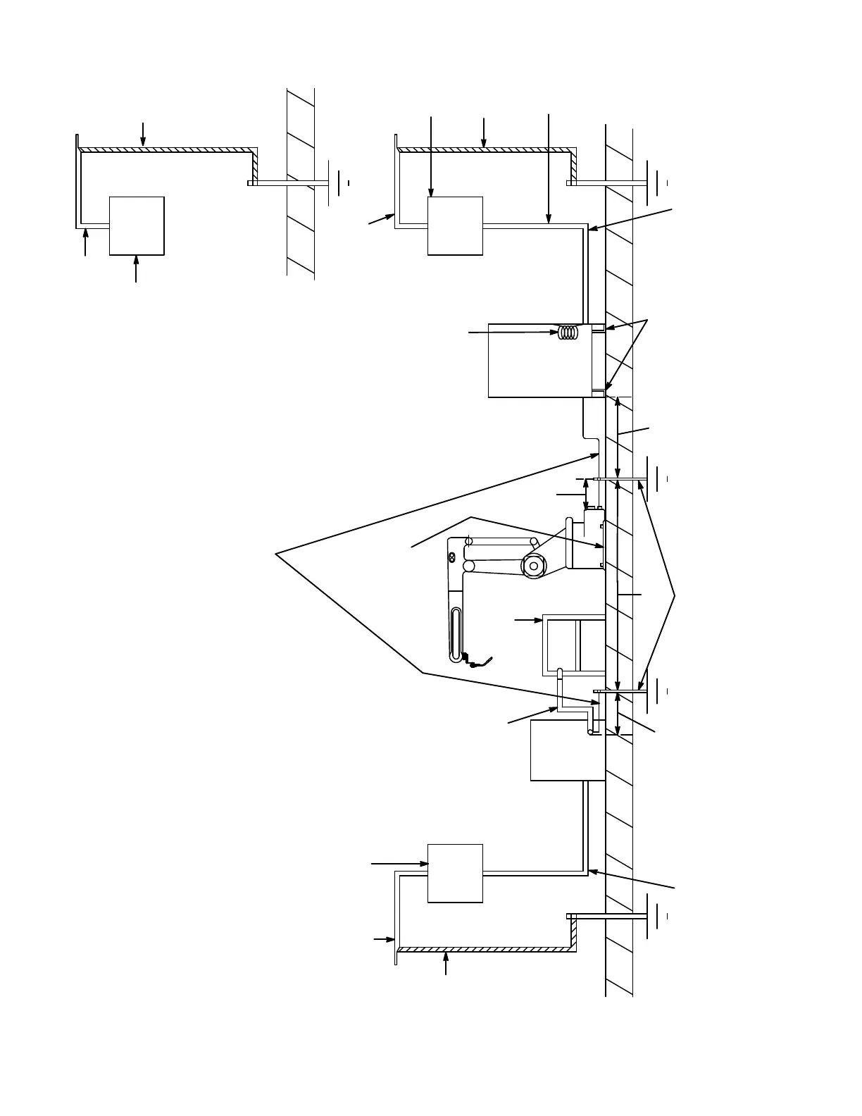
Use Proper Size Input And Ground
Insulating Liner
Strips Under Both
Support Channels
Customer Supplied Driven Ground Rod
Or Separate Earth Ground Connection
Less Than 100 Ohms To Building Ground
Existing
Input Power
Supply Ground
Input Power
Supply Line
Line Disconnect Switch Box
For Input Power To Fixture
Positioning And Peripheral
Equipment
Input Power
Supply Line
Line
Disconnect
Switch Box
If Using
Conduit,
Isolate It
From Robo
Control
Cabinet
Existing
Input Power
Supply Groun
Make Ground
Lead 5 ft. (1.5 m)
To 10 ft. (3 m) Longer
And Coil It Inside
Robot Control
10 ft. (3 m)
Minimum
Work Weld
Cable
Worktable
Make Separate Equipment
Earth Ground Using A Minimum
Of No. 3 Gauge Copper Braided
Cable That Provides A Resistance
Value Less Than 100 Ohms Between
The Component Connection And
The Ground Wire
5 ft.
(1.5 m)
15 ft.
(4.5 m)
5 ft.
(1.5 m)
IMPORTANT: DO NOT mount anything to robot control cabinet.
SB-136 221-
Insulating
Plate
Under Robot
Conductors For The Input Power
Supply Line Voltage
Use Proper Size Input And Groun
Conductors For The Input Powe
Supply Line Voltage
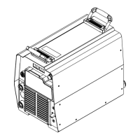
Figure 9-1. Earth Ground Connections To Stationary Robot System Components
 Loading...