TM-246193 Page 17
Invision 352 MPa
input2 2012−05
! Installation must meet all National and
Local Codes − have only qualified per-
sons make this installation.
! Disconnect and lockout/tagout input
power before connecting input con-
ductors from unit. Follow established
procedures regarding the installation
and removal of lockout/tagout
devices.
! Always connect green or green/yellow
conductor to supply grounding termi-
nal first, and never to a line terminal.
NOTICE − The Auto-Line circuitry in this unit
automatically adapts the power source to the
primary voltage being applied. Check input
voltage available at site. This unit can be con-
nected to any input power between 208 and
575 VAC without removing cover to relink the
power source.
See rating label on unit and check input volt-
age available at site.
For Three-Phase Operation
1 Input Power Cord.
2 Disconnect Device (switch shown in the
OFF position)
3 Green Or Green/Yellow Grounding
Conductor
4 Disconnect Device Grounding Terminal
5 Input Conductors (L1, L2 And L3)
6 Disconnect Device Line Terminals
Connect green or green/yellow grounding
conductor to disconnect device grounding ter-
minal first.
Connect input conductors L1, L2, and L3 to
disconnect device line terminals.
7 Over-Current Protection
Select type and size of over-current protec-
tion using Section 4-6 (fused disconnect
switch shown).
Close and secure door on disconnect device.
Follow established lockout/tagout procedures
to put unit in service.
4-8. Connecting 3-Phase Input Power (Continued)
Notes
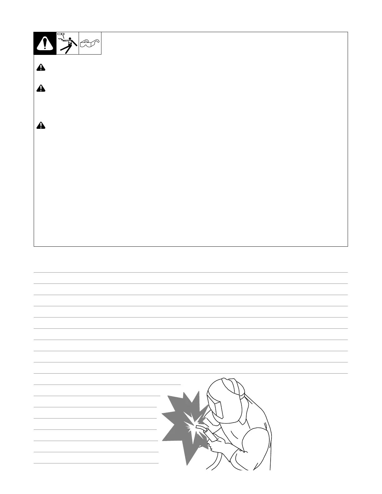
Work like a Pro!
Pros weld and cut
safely. Read the
safety rules at
the beginning
of this manual.

 Loading...